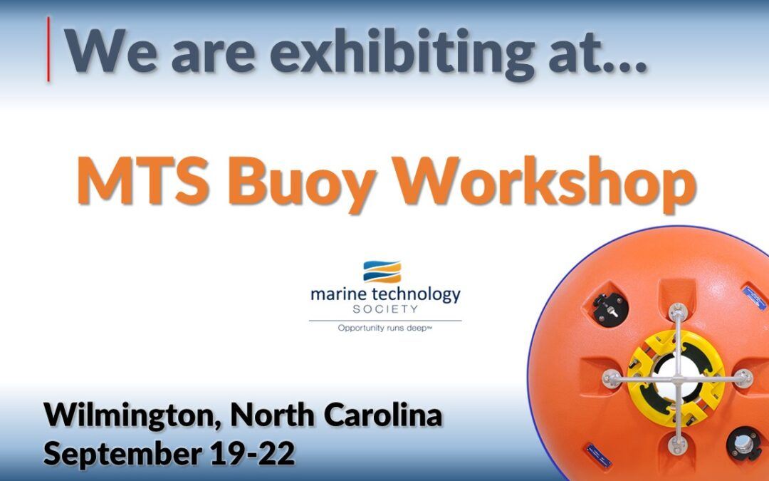
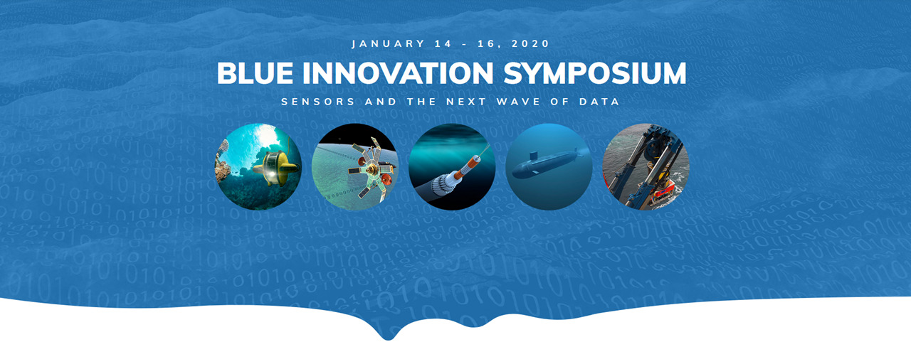
2026 Buoy Workshop

Exhibiting
DeepWater Buoyancy is exhibiting at the 16th MTS Buoy Workshop.
The event is being held March 23-26 at The University of South Florida, St. Petersburg Campus, College of Marine Science.
Event Details from MTS
You are cordially invited to join us for the 16th MTS Buoy Workshop sponsored by the Marine Technology Society (MTS) to present and share your buoy-related work and projects to all attendees.
Since the 1960s, these workshops have covered the technology of oceanographic, weather, and other buoy systems. Originally based on the suggestion and support by the Office of Naval Research, buoy workshops have been organized and supported every two years since 1996 to foster communication and exchange between designers, assemblers, operators, and users of buoy systems.
This year’s Workshop, presented in partnership with the Florida Institute of Oceanography and the University of South Florida-College of Marine Science, begins with a pre-event seminar and workshop presented by ProteusDS on Monday afternoon, March 23, followed by an evening Ice-Breaker. The Speaker Program runs from Tuesday morning, March 24, through Thursday afternoon, March 26 (concluding around 5:00 p.m.). On Wednesday afternoon, participants will tour host facilities engaged in active buoy projects, with a networking reception to follow that evening.
Learn more about the event at MTS Buoy Workshop

At the Workshop
If attending, please be sure to visit with Dan Cote, our Sales Manager
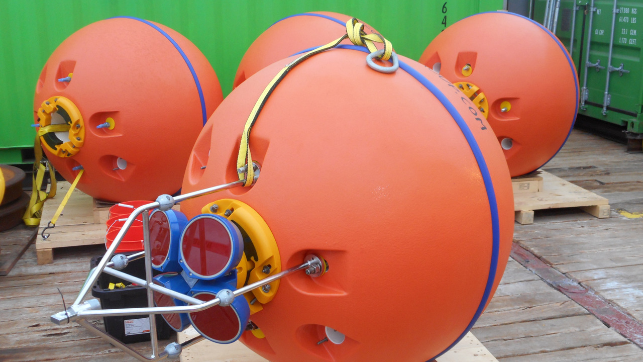
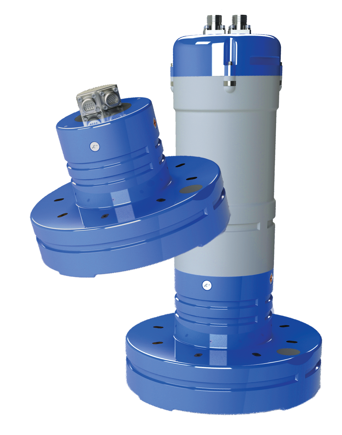
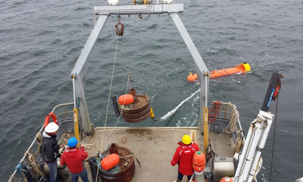
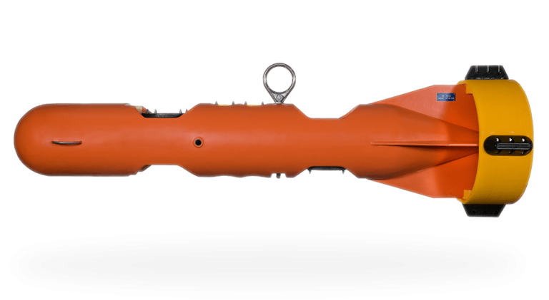
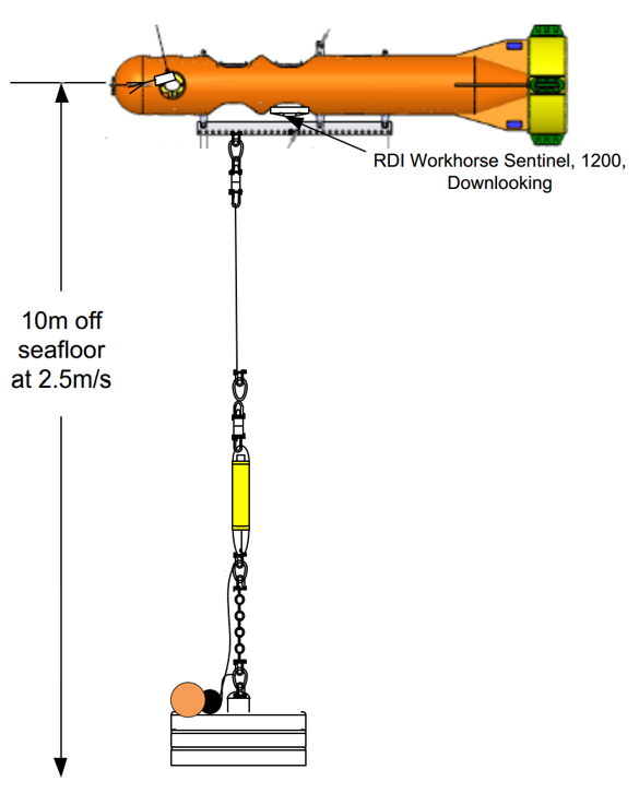
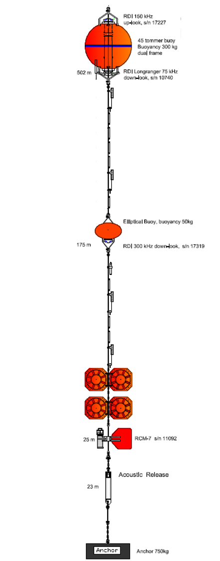
At the event, we will be highlighting our full range of products for the ocean science community, including our line of midwater ADCP buoys.

About DeepWater Buoyancy, Inc.
DeepWater Buoyancy creates subsea buoyancy products for leading companies in the oceanographic, seismic, survey, military and offshore oil & gas markets. Customers have relied on our products for over forty five years, from the ocean surface to depths exceeding six thousand meters.
Learn more at www.DeepWaterBuoyancy.com