/category/all-products Archive


Exhibiting at IPF 2024

Exhibiting at IPF 2024

Oceantic Network Offshore Wind Event - IPF 2024

Exhibiting

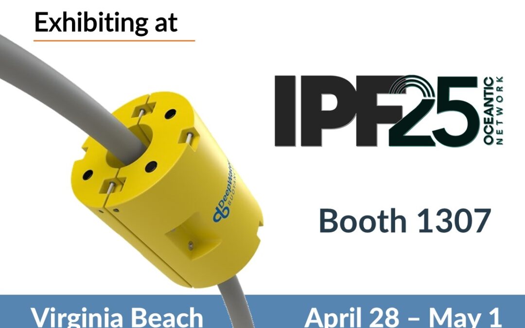
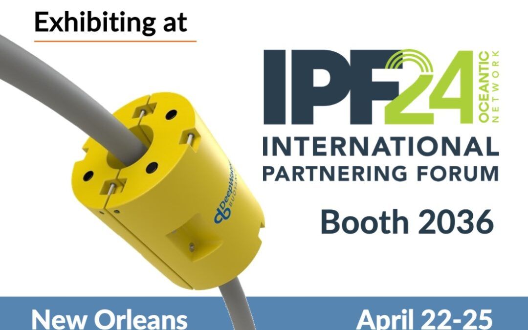
DeepWater Buoyancy is exhibiting at Oceantic Network’s International Partnering Forum (IPF) 2024 conference.

The event will take place April 22-25, 2024 at the New Orleans Ernest N. Morial Convention Center in New Orleans, Louisiana.

About the Event

The International Partnering Forum (IPF), hosted by Oceantic Network (formerly the Business Network for Offshore Wind), is the premier offshore wind energy conference in the Americas. Industry experts from around the world converge to share best business practices, the most advanced technical and scientific findings, and policy updates impacting offshore wind. IPF connects global leaders and businesses in the supply chain, offers unparalleled networking opportunities, and delivers the most timely and relevant updates on the industry, from technology and policy to safety and siting.

Located in the heart of America’s offshore energy industry, New Orleans will host 2024 IPF just as the Gulf of Mexico begins developing its offshore wind market. Taking place April 22-25, 2024, IPF offers registrants a vast array of networking opportunities to grow your business, including the popular WindMatch™ program. With the rapid expansion of offshore wind, IPF attendance helps secure your place as a leader in the industry.

Learn more HERE.


Oceantic Network IPF 2024

Who is the Oceantic Network?

At the Oceantic Network (formerly the Business Network for Offshore Wind), our driving purpose is to inform, coordinate, and mobilize human ingenuity, enterprise, and labor to take advantage of the urgent need to tap the vast renewable energy resources that lie offshore in the world’s oceans. The collective, coordinated efforts of our members equip communities and nations to accelerate the transition to clean energy and create economic opportunities.

Over the past ten years, the Network has grown along with the industry, changing its name to expand and include industry sectors. At its ten-year mark, the Network continues to look forward and set the pace for the industry; that includes an expanded view of what offshore wind can provide the energy mix. Offshore wind is the gateway to other ocean renewables, including green hydrogen, wave energy, and more. Offshore wind as an industry will remain the main focus of the Network; however we are expanding our scope to grow and adapt as the industry does the same. With this enlarged focus, the Network changed its name from the Business Network for Offshore Wind to the Oceantic Network.

Learn More HERE.

At the Booth

David Capotosto (Director of Business Development, DeepWater Buoyancy) will be in attendance at our Booth – #2036.  He will be joined by Kurt Fromhurst of Waters and David, Company, DeepWater Buoyancy’s Gulf Coast sales representatives.  The company will be highlighting its offerings for floating offshore wind projects.

  • Interarray Cable Buoyancy
  • Mooring Line Buoyancy
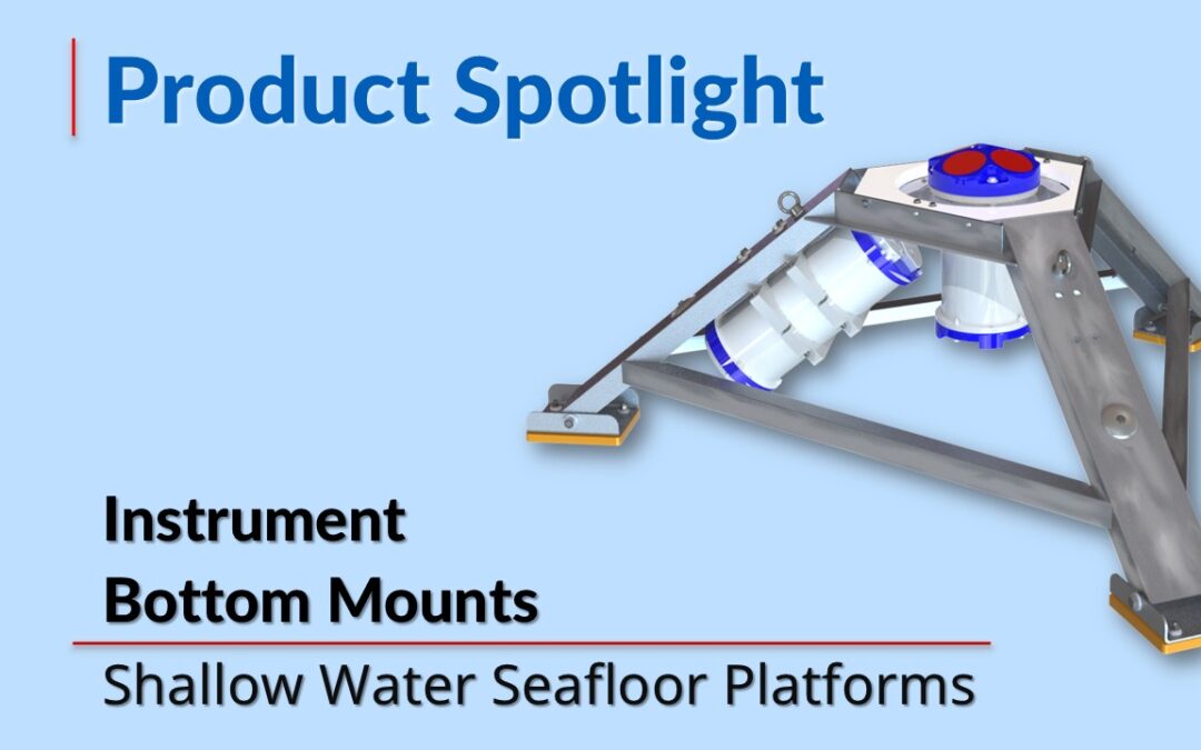
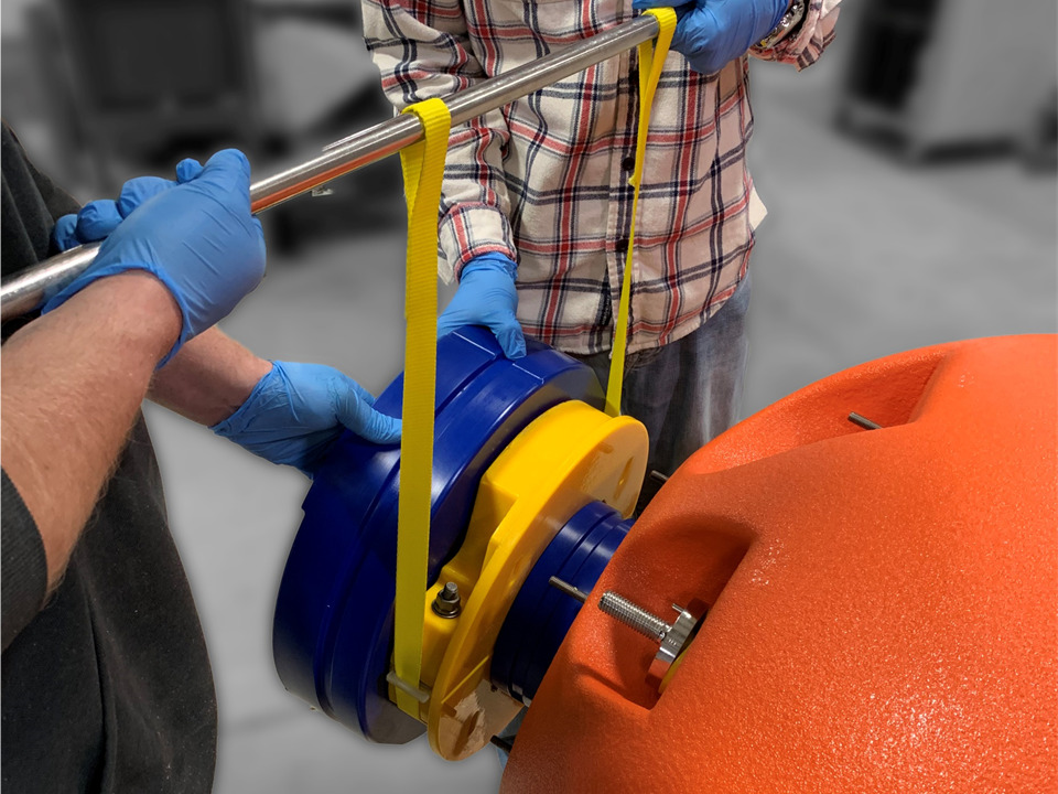
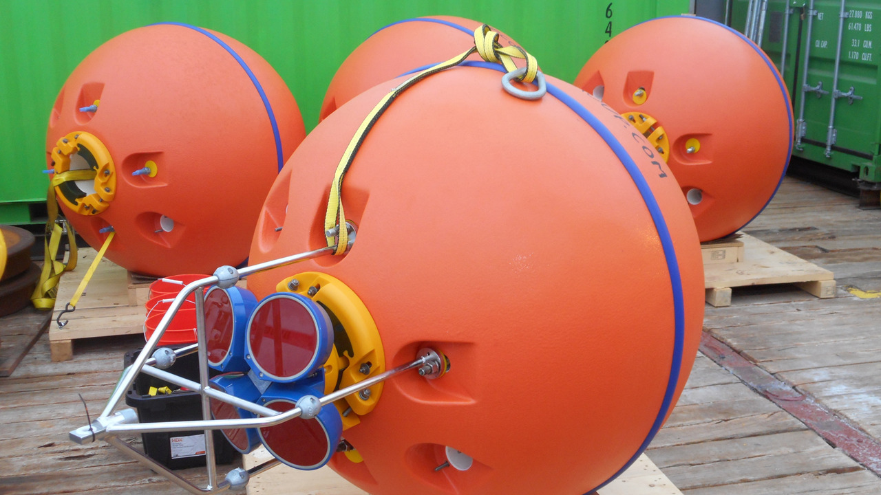
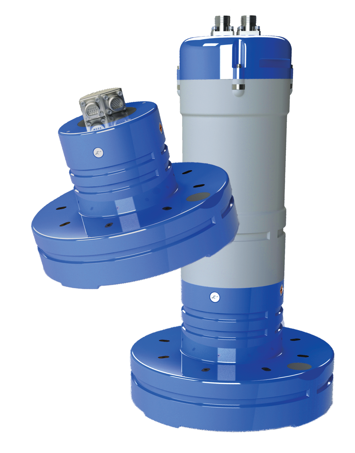
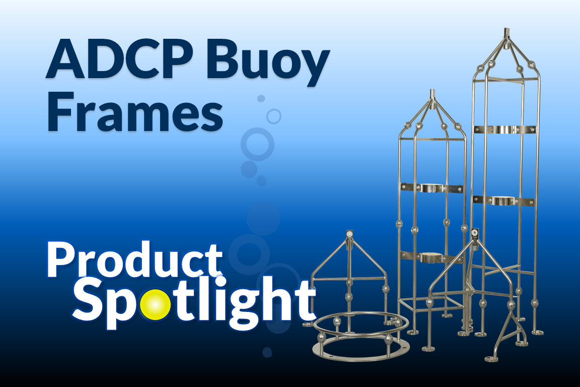
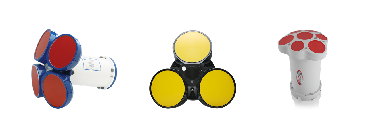
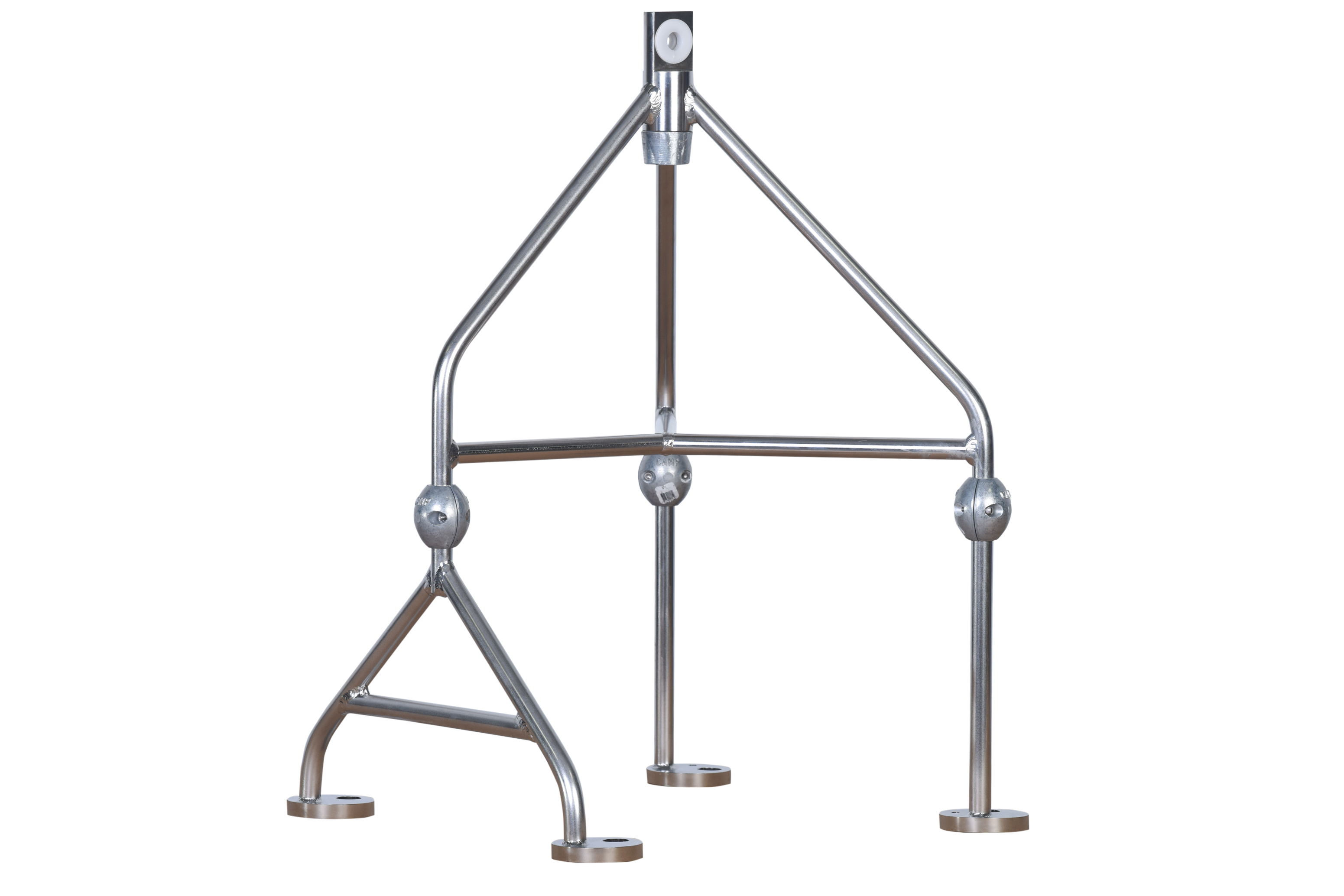
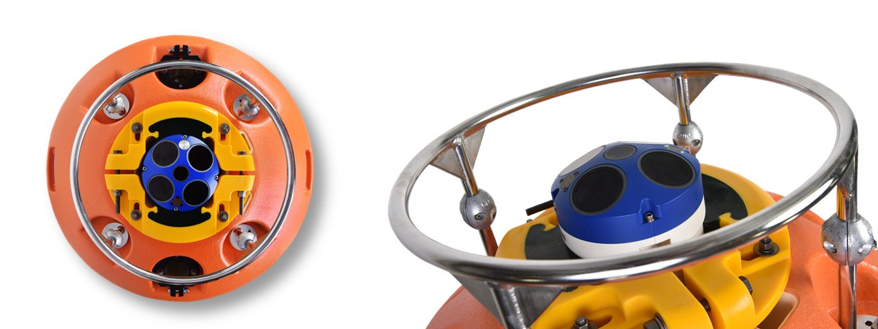
  • Full line of Buoyancy and Deployment Platforms for Subsea Instrumentation

See our full product offering HERE.

Floating Offshore Wind Interarray Cable Buoyancy

About DeepWater Buoyancy, Inc.

DeepWater Buoyancy creates subsea buoyancy products for leading companies in the oceanographic, seismic, survey, military and offshore oil & gas markets.   Customers have relied on our products for over forty-five years, from the ocean surface to depths exceeding six thousand meters.

Learn more at www.DeepWaterBuoyancy.com

Product Spotlight – MiniMod™ Small Modular Buoy

Product Spotlight – MiniMod™ Small Modular Buoy

Product Spotlight - MiniMod Small Modular Buoy

DeepWater Buoyancy is one of the world’s premier producers of subsea buoyancy products. Its portfolio of products include standard and custom solutions for all subsea markets including, ocean science, offshore energy, and military.

This month’s product spotlight focuses on one of DeepWater Buoyancy’s most versatile offerings: MiniMod™ Small Modular Buoys. Our customizable MiniMod™ solutions provide incremental buoyancy ideal for precision operations.

Modular Buoyancy Solutions for Light Offshore Applications

MiniMod™ modular buoys keep your offshore operations running smoothly. The compact design features an extremely durable body and fixtures to withstand harsh marine conditions, including saltwater corrosion, and high subsea pressures.

Its strength lies in its modular design. Simply add or remove blocks to adjust buoyancy as needed. Use MiniMod™ with ROVs and other marine equipment to achieve optimal load requirements with ease.

MiniMod™ Small Modular Buoys Benefit a Variety of Marine Operations

At DeepWater Buoyancy, we know that floatation requirements vary widely based on equipment weight, environmental conditions, vessel characteristics, and more. Our modular buoy design lets you modify buoyancy incrementally to account for these variable criteria.

Quick buoyancy adjustments with MiniMod™ modules help speed equipment deployment and hasten installations so you can minimize downtime and keep your offshore projects on track.

Our MiniMod™ Small Modular Buoys are ideal for light offshore operations with highly accurate lift value requirements. Applications that benefit from our MiniMod™ adjustable buoys include:

  • Deep sea equipment installation
  • Remotely operated vehicle (ROV) deployment
  • Offshore equipment repairs and maintenance
  • Mining, oil, and gas exploration operations
  • Load handling
  • Suspended moorings

Our easy-to use modular buoy blocks are also customizable. End-plates and thru hardware provide divers and other workers with user-friendly modification methods. User-friendly hardware lets your divers and other marine workers spend less time in the water, which further enhances your operation’s safety and efficiency.

Whether you need an adjustable buoy for a short-term project or long-term flotation, the MiniMod™ has the durability and flexibility you need.

MiniMod™ Small Modular Buoy

Customer Experience Highlight

In an excellent example of the advantages our MiniMod™, one of our clients recently used the modular buoy to boost buoyancy and balance underwater loads when tooling suites and steel tube flying leads (STLVs) proved too heavy for the customer’s ROV.

By incorporating the MiniMod™ equipment, the customer was able to tailor loads to accommodate the ROV’s capacity and lighten the part for easy of handling.

MiniMod Modular Buoys Are Durable and Easy to Use

The MiniMod™ modular buoy design is ideal for lighter applications. Our standard 7-modul buoy offers up to 325 kg of buoyancy and is rated for depths down to 6000 meters.

Each module features our proprietary high-strength DeepTec® solid syntactic foam with an abrasion-resistant coating of polyurethane elastomer for optimal durability. You can rely on the MiniMod to withstand challenging marine environments and rough handling.

Synthetic straps hold the syntactic foam modules together, enhancing buoyancy while preventing metal hardware corrosion. The straps also make the interlocking modules easier to handle, so you can quickly add or remove blocks as needed throughout your operation.

The MiniMod™’s rugged design and interlocking modules ensure years of trouble-free use for even the most extreme marine environments. Contact DeepWater Buoyancy to schedule a consultation and learn how MiniMod™ Small Modular Buoys can streamline your offshore operations.

About DeepWater Buoyancy, Inc.

DeepWater Buoyancy creates subsea buoyancy products for leading companies in the oceanographic, seismic, survey, military and offshore energy markets.   Customers have relied on our products for over forty years, from the ocean surface to depths exceeding six thousand meters.

Learn more at DeepWaterBuoyancy.com

DeepWater Buoyancy Logo
Floating Wind Solutions 2024

Floating Wind Solutions 2024

Tekmar and DeepWater Buoyancy Floating Wind Solutions 2023

Exhibiting

DeepWater Buoyancy will be exhibiting at the Floating Wind Solutions 2024 conference.

The event will take place from February 5-7 at the Hilton Americas in Houston, Texas.

About the Event

Floating Wind Solutions Conference & Exhibition 2024 will showcase the many capabilities of the established Global Offshore Supply Chain and create a platform for bridging Supply and Demand while facilitating development of this industry. Floating Wind Solutions’ mission is to utilize this platform to bring together the many critical players within the Wind and Offshore industries enabling accelerated adoption of Floating Wind Energy globally.  This premier event’s primary goal is to accelerate the Energy Transition, by focusing on the industrialization and commercialization of Floating Wind Energy.  A world class Advisory Board ensures a world class program that is extremely focused on the principles of this mission.

If you have any questions about the conference program, please contact Andrew Chadderton (andrew.chadderdon@questfwe.com).

Find the Program Agenda here – floatingwindsolutions.com/agenda

Learn more at – floatingwindsolutions.com

Floating Winds Solutions Offshore Wind Event 2024

At the Booth

DeepWater Buoyancy’s Sales Manager, Dan Cote, and Director of Business Development, David Capotosto, will be in attendance at our Booth #505 where they will be highlighting the company’s buoyancy offerings for floating wind platforms.

These include:

DeepWater Buoyancy Offshore Floating Wind Cable Buoy

About DeepWater Buoyancy, Inc.

DeepWater Buoyancy creates subsea buoyancy products for leading companies in the oceanographic, seismic, survey, military and offshore oil & gas markets.   Customers have relied on our products for over forty years, from the ocean surface to depths exceeding six thousand meters.

Learn more at www.DeepWaterBuoyancy.com

Mooring Matters: The C-Streams Project

Mooring Matters: The C-Streams Project

Mooring Matters - C-Streams Project - October 2023 Comparison

This month’s technical highlight discusses the C-Streams Project – Studying How the Gulf Stream Affects the Climate System.

The C-Streams Project is a collaborative research project by The University of Liverpool, the University of Miami, the National Oceanography Center, the Scottish Association for Marine Science, and the British Antarctic Survey.

The project deployed a variety of scientific instrumentation into the Gulf Stream on a customized DeepWater Buoyancy StableMoor® Mooring Buoy. The C-Streams Project team will use these instruments to monitor the flow of carbon and nutrients in the Gulf Stream. Project scientists hope the results will provide insight into the Gulf Stream’s role in the ocean carbon cycle and how it affects global climate change.

The C-Streams Project

The C-Streams Project is a four-year, £4 million collaborative research project supported by the Natural Environment Research Council (NERC) and the US National Science Foundation (NSF).

Headed by Professor Ric Williams of The University of Liverpool, the C-Streams Project will observe how the current speed, turbulence, and other factors can affect carbon and nutrient circulation in the Atlantic Ocean.

Most ocean carbon exchange occurs through two mechanisms:

  • Phytoplankton photosynthesis, which requires nutrient-dense water
  • Chemical exchange between seawater and atmospheric carbon dioxide

By observing the flow of nutrients and carbon in the Gulf Stream under varying conditions, the C-Stream Project seeks a deeper understanding of these dynamic carbon exchange processes.

“We will use this data alongside the latest state-of-the-art ocean and climate models to provide us with some answers as to how the Gulf Stream affects the carbon cycle, a hitherto ignored aspect of the climate problem,” explains Professor Ric Williams.

The Deployment

Deploying sensitive instrumentation in the turbulent Gulf Stream involves significant coordination between scientists, mooring specialists, sailors, and engineers. Instruments require stability to ensure consistent readings, which means a mooring system capable of withstanding the Atlantic Ocean’s changeable and sometimes violent weather.

To launch the C-Streams Project, scientists successfully deployed two DeepWater Buoyancy StableMoor® Mooring Buoys holding a variety of scientific instrumentation into the Gulf Stream through the Florida Straits.

Thanks to the captain and crew of the Walton Smith, principal scientist Professor Lisa Beal (University of Miami), the mooring expertise of Eduardo Jardim (University of Miami), Dr. Pete Brown and Darren Rayner (National Oceanography Centre), and the project research team, the launch went smoothly.

The team also deployed three biogeochemical moorings designed by Darren Rayner. These additional moorings included buoys, sensors, and autonomous vehicles.

Over the next four years, the deployed equipment will obtain data, take measurements, and collect samples to assess how the Gulf Stream current affects nutrients and carbon transport. The C-Stream Project team will analyze this information to determine whether the Gulf Current’s interactions enhance or inhibit the ocean’s carbon dioxide uptake.

On-deck View of the StableMoor Mooring Buoy for Study of Gulf Stream
 Photos courtesy of University of Miami mooring technician Eduardo Jardim.

The Buoy

It takes a special buoy to provide a stable platform for instrumentation in high-speed ocean currents like the Gulf Stream. Specifically engineered for these types of applications, DeepWater Buoyancy’s StableMoor® buoys provide excellent mooring stability in extreme flow environments.

With a tapered cylindrical design, the StableMoor® reduces drag and minimizes mooring inclination and excursions. The decreased frontal area provides superior dynamic stability in high current areas compared to traditional spherical buoys. A high-strength GRP tail and stainless-steel mooring swivel ensure optimal flexibility and stability in the Gulf Stream’s strong, changeable currents.

David Capotosto, DeepWater Buoyancy’s Director of Business Development, is excited to see how the project evolves. “It is always amazing to see how ocean scientists and engineers utilize our products,” he says. “This project showcases our team’s ability to deliver on our design philosophy: to provide our end users with a product that is fit to their application.”

About DeepWater Buoyancy, Inc. DeepWater Buoyancy, Inc., located in Maine USA, provides subsea buoyancy products for offshore energy, oceanographic, military, and technology companies around the world. Customers have relied on our products for over forty years, from the ocean surface to depths exceeding six thousand meters. Learn more at DeepWaterBuoyancy.com
DeepWater Buoyancy Logo
Mooring Matters: Fixed vs. Floating Offshore Wind Turbines

Mooring Matters: Fixed vs. Floating Offshore Wind Turbines

Tekmar Secures US Wind CPS Order

For the next installment in our series of technical articles, we have asked our colleagues at Tekmar Group to give us a primer on Fixed versus Floating Offshore Wind Turbines.  

The article looks at the benefits and challenges of each.

Harnessing the Power of the Winds

As the world transitions towards cleaner and more sustainable energy sources, offshore wind power has emerged as a critical player in the renewable energy sector. While fixed offshore wind turbines have been the predominant choice for harnessing wind energy over the years, recent advancements have introduced a new contender: floating offshore wind turbines.

This article will explore the differences between fixed and floating offshore wind turbines, examining their advantages, challenges, and potential for revolutionizing renewable energy generation.

Fixed Offshore Wind Turbines: Stability and Reliability

Fixed Offshore Wind Turbines, as the name suggests, have a direct rigid connection to the seabed, so they are ‘fixed’ in a permanent static position. These structures consist of large wind turbines mounted on monopile, jacket, or gravity-based foundations, typically installed in water depths up to 60 meters. Fixed turbines have been widely deployed across Europe, where the industry has rapidly matured.

One of the significant advantages of Fixed Offshore Wind Turbines is their stability. Being directly fixed to the seabed provides a stable static structure, allowing these turbines to withstand harsh weather conditions, including strong winds and rough seas. Fixed turbines offer relatively straightforward installation and maintenance due to their permanent positioning. This factor reduces maintenance costs and reliability, enabling consistent power generation compared to more dynamic structures.

Fixed and Floating Offshore Wind Turbine Graphic

Floating Offshore Wind Turbines: Unlocking Deep Waters

On the other hand, Floating Offshore Wind Turbines offer a solution to harness wind energy in deeper waters, where fixed turbines are impractical. These turbines are not static or directly affixed to the seabed but moored in place using offset anchors or foundations and mooring lines. Floating turbines are particularly suitable for water depths exceeding 60 meters and can operate in areas with challenging seabed conditions.

One of the primary advantages of floating offshore wind turbines is their ability to tap into wind resources in locations inaccessible for fixed turbines. This opens up vast areas of deep waters worldwide for wind energy development. Floating turbines also benefit from stronger and more consistent winds found farther offshore, leading to potentially higher energy production. Moreover, installing floating turbines further from the shore reduces visual impacts and mitigates potential conflicts with other marine activities.

Offshore Wind Speed NREL

Challenges and Innovations

While both Fixed and Floating Offshore Wind Turbines have advantages, they also face distinct challenges. For fixed turbines, the major limitation lies in water depth constraints, limiting their deployment to relatively shallow waters.

Although promising, floating offshore wind turbines face challenges related to their relatively nascent stage of development. The technology requires further refinements to enhance stability, reduce costs, and improve power output. However, significant progress has been made in recent years, with several pilot projects and demonstration sites showcasing the potential of floating turbines. Innovative floating foundation designs offer improved stability and reduced motion on high seas.

Future Prospects

The emergence of Floating Offshore Wind Turbines presents exciting possibilities for expanding wind energy capacity. Countries with limited shallow coastal areas can tap into abundant wind resources by venturing into deeper waters. Additionally, advancements in floating turbine technology are expected to lead to cost reductions, increased reliability, and scalability.

Meanwhile, Fixed Offshore Wind Turbines continue to be a reliable and maturing technology that has proven its worth over the years. They will likely remain dominant for near-shore projects and regions with suitable seabed conditions.


Tekmar DeepWater Products for Offshore Wind
About Tekmar Group

Tekmar Group plc, based in Darlington UK, provides market-leading technology and services to the global offshore energy markets through its primary operating companies Ryder Geotechnical Limited, AgileTek Engineering Limited, Subsea Innovation Limited, Tekmar Energy Limited, and Pipeshield International Limited.

Learn more at www.TekmarGroup.com

DeepWater Buoyancy Logo
About DeepWater Buoyancy, Inc.

DeepWater Buoyancy, Inc., located in Maine USA, provides subsea buoyancy products for offshore energy, oceanographic, military, and technology companies around the world. Customers have relied on our products for over forty years, from the ocean surface to depths exceeding six thousand meters.

Learn more at DeepWaterBuoyancy.com

DeepWater Buoyancy Logo
H2O Conference 2023

H2O Conference 2023

H2O Conference Canada 2023

Exhibiting

DeepWater Buoyancy will be showing with Canadian Representative group, DASCO Equipment, at the 2023 H2O Home to Overseas Conference.

Please stop by booth 504 to visit Matt Davis and team, as well as DeepWater Buoyancy’s Director of Business Development, David Capotosto.

The event will take place Monday, June 12-14, 2023, at the Halifax Convention Center in beautiful Atlantic Canada.

About the Event

The Home to Overseas Conference, is rapidly becoming Canada’s premier event for the ocean technology sector and is attracting significant international participation covering sectors such as marine defense, marine energy (offshore extractive and renewable), marine environmental monitoring, marine transportation, aquaculture, fisheries, and marine tourism.

Learn more here… www.h2oconference.ca 

H2O Conference Atlantic Canada 2023

About DASCO Equipment, Inc.

DASCO Equipment is Canada’s leader in oceanographic, hydrometric & marine survey technologies.. The company’s primary business is the sales, and sales support, of this equipment, however, they also maintain a large pool of rental equipment, including acoustic doppler current profilers, multibeam and single beam echosounders, marine GPS and GNSS systems and marine survey software packages.

Learn more at dascoei.ca

dasco-equipment-canada

About DeepWater Buoyancy, Inc.

DeepWater Buoyancy creates subsea buoyancy products for leading companies in the oceanographic, seismic, survey, military and offshore oil & gas markets.   Customers have relied on our products for over forty years, from the ocean surface to depths exceeding six thousand meters.

Learn more at www.DeepWaterBuoyancy.com

Ocean Business 2023

Ocean Business 2023

Ocean Business 2023

Exhibiting

DeepWater Buoyancy will be exhibiting at Ocean Business 2023. The event will take place April 18-20, 2023 at the National Oceanography Centre in Southampton, UK.

Please visit Dan Cote (Sales Manager) and Jordan Tremblay (Sales Engineer) at Booth S10.

About the Event

Ocean Business 2023 is the global meeting place for ocean science and technology professionals.

Connect with thousands of the industry’s brightest minds, and share ideas to help define the future of ocean technology.

From cutting-edge surveying innovation to the latest marine autonomous systems, you’ll find hundreds of solutions to transform your business in 2023 and beyond.

Learn more here… www.oceanbusiness.com

Ocean Business 2023 Banner

About DeepWater Buoyancy, Inc.

DeepWater Buoyancy creates subsea buoyancy products for leading companies in the oceanographic, seismic, survey, military and offshore oil & gas markets.   Customers have relied on our products for over forty years, from the ocean surface to depths exceeding six thousand meters.

Learn more at www.DeepWaterBuoyancy.com

IPF 2023

IPF 2023

Tekmar and DeepWater Buoyancy  IPF 2023

Exhibiting

DeepWater Buoyancy and Tekmar Group are exhibiting together at the Business Network for Offshore Wind’s International Partnering Forum (IPF) 2023 conference.

The event will take place March 28-30, 2023 at the Baltimore Convention Center in Baltimore, Maryland

About the Event

The International Offshore Wind Partnering Forum (IPF) is the premier offshore wind energy conference in the Americas. Hosted by the Business Network for Offshore Wind, IPF connects global leaders and businesses in the supply chain, offers unparalleled networking opportunities, and delivers the most timely and relevant updates on the industry, from technology and policy, to safety and siting.

In addition to plenary presentations and cutting-edge workshops from public officials and industry leaders, IPF offers registrants a wide array of networking opportunities to grow your business, including the popular WindMatch™ program. With the rapid expansion of offshore wind, IPF attendance helps secure your place as a leader in the industry.

2023 marks the tenth anniversary of IPF as it returns to where it all started:  Baltimore, Maryland

With its central location and world-class harbor in Baltimore, Maryland is moving forward with offshore wind. With over 2 GW in deployment, planned facilities or towers, monopiles and cables, Maryland will be a hub of manufacturing and logistical activity for the U.S. offshore wind industry.

IPF 2023 Offshore Wind Conference Infographic

Who is the Business Network for Offshore Wind?

The Business Network for Offshore Wind is a nonprofit, educational organization with a mission to develop the offshore wind renewable energy industry and its supply chain. The Network partners with industry and government to build an innovative supply chain that will create and sustain jobs, benefiting local economies and ensuring a cost-effective clean energy portfolio. We advance this through collaboration, education, and innovation, bringing together global developers, policymakers, academia, and leading experts to grow this new and vital offshore wind industry that provides a practical solution to climate change and creates well-paying jobs.

We are the offshore wind experts. Join us by becoming a member.

If you are involved in the offshore wind industry, you do not want to miss IPF.

If you have questions about your registration, please contact the Network’s registration team at ipfregistration@offshorewindus.org for the quickest response.  You can also contact the 2023 IPF Call Center: (972) 349-7620.   Call Center Hours: 7:00 a.m. – 6:00 p.m. CST, Monday-Friday

Learn more at the website – www.offshorewindus.org/2023ipf

At the Booth

Gary Howland (Group Sales Director, Tekmar Group), Fraser Gibson (Managing Director, Ryder Geotechnical Ltd) and David Capotosto (Director of Business Development, DeepWater Buoyancy) will be in attendance at our Booth – #450.  The companies will be highlighting their combined offerings in support of floating offshore wind projects.

Enabling the Future of Floating Wind

  • Complete Engineering & Product Offering for Inter-Array & Export Cables
  • Extensive Track Record of over 100 Offshore Wind Projects
  • Vast Experience in Engineering & Product Design for Offshore Energy Markets

Learn about the partnership HERE

See the Tekmar Partner Products page HERE

Tekmar Group & DeepWater Buoyancy Offshore Wind Banner

About Tekmar Group

Tekmar Group plc, based in Darlington UK, provides market-leading technology and services to the global offshore energy markets through its primary operating companies Ryder Geotechnical Limited, AgileTek Engineering Limited, Subsea Innovation Limited, Tekmar Energy Limited, and Pipeshield International Limited.

Learn more at www.TekmarGroup.com

DeepWater Buoyancy Logo

About DeepWater Buoyancy, Inc.

DeepWater Buoyancy creates subsea buoyancy products for leading companies in the oceanographic, seismic, survey, military and offshore oil & gas markets.   Customers have relied on our products for over forty years, from the ocean surface to depths exceeding six thousand meters.

Learn more at www.DeepWaterBuoyancy.com

Floating Wind Solutions 2023

Floating Wind Solutions 2023

Tekmar and DeepWater Buoyancy Floating Wind Solutions 2023

Exhibiting

DeepWater Buoyancy and Tekmar Group are exhibiting together at the Floating Wind Solutions 2 conference.

The event will take place from January 30 to February 1 at the Marriott Marquis in Houston Texas.

About the Event

Floating Wind Solutions (FWS ’23) is the ultimate opportunity for those who are presently involved in or seeking entry into floating wind. FWS facilitates network opportunities with the right experienced people while gaining knowledge of the technical solutions available. Floating Wind Solutions’ mission is to utilize this platform to bring together the many critical players within the wind and offshore industries enabling accelerated adoption of Floating Wind Energy globally. This premier event’s primary goal is to accelerate the Energy Transition, by focusing on the industrialization and commercialization of Floating Wind Energy. A world class Advisory Board ensures that the program maintains its sharp focus on the principles of the mission.

Exceptional growth in the harvesting of Floating Wind Energy will be reliant upon the technology and experience of companies historically focused on the offshore Supply Chain. With few exceptions, these companies are the only ones who have ever designed, constructed or installed permanently moored structures of any kind. In addition, traditional Major Offshore Energy Operators are leading investors, developers and operators of Floating Wind Energy Projects.

If you have any questions about the conference program, please contact Andrew Chadderton (andrew.chadderdon@questfwe.com).

Learn more at the website – https://floatingwindsolutions.com/

Floating WInd Solutions 2023 Banner

At the Booth

Tekmar Group’s Howard Curtis and DeepWater Buoyancy’s David Capotosto, will be in attendance at our Booth – #503.  At the booth, the companies will be highlighting their combined offerings in support of floating offshore wind projects.

Enabling the Future of Floating Wind

  • Complete Engineering & Product Offering for Inter-Array & Export Cables
  • Extensive Track Record of over 100 Offshore Wind Projects
  • Vast Experience in Engineering & Product Design for Offshore Energy Markets
Tekmar Group Offshore Wind Subsea Field

About Tekmar Group

Tekmar Group plc, based in Darlington UK, provides market-leading technology and services to the global offshore energy markets through its primary operating companies Ryder Geotechnical Limited, AgileTek Engineering Limited, Subsea Innovation Limited, Tekmar Energy Limited, and Pipeshield International Limited.

Learn more at www.TekmarGroup.com

DeepWater Buoyancy Logo

About DeepWater Buoyancy, Inc.

DeepWater Buoyancy creates subsea buoyancy products for leading companies in the oceanographic, seismic, survey, military and offshore oil & gas markets.   Customers have relied on our products for over forty years, from the ocean surface to depths exceeding six thousand meters.

Learn more at www.DeepWaterBuoyancy.com

Tekmar Secures Contract for US Wind Project

Tekmar Secures Contract for US Wind Project

Tekmar Secures US Wind CPS Order

Tekmar Group Secures Significant Contract for a US Offshore Wind Project

We are pleased to announce that our UK partner, Tekmar Group, has been awarded a significant contract for Cable Protection Systems (CPS) for an offshore wind farm project in the U.S.

The company announced the award on May 25th.


The Contract

Under the contract, Tekmar will provide an integrated engineering solution, including Cable Protection Systems (CPS), for the offshore wind project across the pond.

The CPS is expected to be delivered in 2023, according to the company.

“This landmark contract award strengthens our position in the US offshore wind market and represents an important milestone in expanding our geographical presence, a key driver of our growth strategy”, said Alasdair MacDonald, CEO of Tekmar Group, who also added that the contract built on the company’s recent contract momentum, including the Dogger Bank Wind Farm.


Work in the US

In the U.S., the company supplied Seaway 7 with TekLink cable protection systems and TekDuct cable crossing protection for the now-operational 12 MW Coastal Virginia Offshore Wind (CVOW) demonstration project.

The U.S. currently has two commercial-scale offshore wind farms under construction: Vineyard Wind 1 in Massachusetts and South Fork in New York.


Tekmar Partner Product Page

Working with DeepWater Buoyancy

Last year, Tekmar signed a Memorandum of Understanding (MoU) with the DeepWater Buoyancy for collaboration in the offshore wind sector.  While the partnership with DeepWater Buoyancy is focused on the US Offshore Floating Wind market, it also involves supporting Tekmar’s organic growth strategy by strengthening its presence and manufacturing capability in the US bottom-fixed offshore wind market.  The arrangement also provides DeepWater Buoyancy with greater access to the European market.

Recently, Tekmar and DeepWater Buoyancy worked together to deliver a first of a kind solution consisting of buoyancy and ballast for a thermoplastic composite pipe.  Learn more here… LINK  or here…LINK

Learn about the joint offerings for the US Supply Chain here… LINK

About Tekmar Group

Tekmar Group plc, based in Darlington UK, provides market-leading technology and services to the global offshore energy markets through its primary operating companies Ryder Geotechnical Limited, AgileTek Engineering Limited, Subsea Innovation Limited, Tekmar Energy Limited, and Pipeshield International Limited.

Learn more at www.TekmarGroup.com

DeepWater Buoyancy Logo
About DeepWater Buoyancy, Inc.

DeepWater Buoyancy, Inc., located in Maine USA, provides subsea buoyancy products for offshore energy, oceanographic, military, and technology companies around the world. Customers have relied on our products for over forty years, from the ocean surface to depths exceeding six thousand meters.

Learn more at DeepWaterBuoyancy.com

DeepWater Buoyancy Logo
IPF 2022

IPF 2022

Tekmar and DeepWater Buoyancy  IPF 2022

Exhibiting

DeepWater Buoyancy and Tekmar Group are exhibiting together at the Business Network for Offshore Wind’s International Partnering Forum (IPF) 2022 conference.

The event will take place April 26-28, 2022 at the Atlantic City Convention Center in Atlantic City, New Jersey.

About the Event

The International Offshore Wind Partnering Forum (IPF) is the premiere offshore wind energy conference in North America. Hosted by the Business Network for Offshore Wind, IPF connects global leaders and businesses in the supply chain, offers unparalleled networking opportunities, and delivers the most timely and relevant updates on the industry, from technology and policy, to safety and siting.

IPF 2022 Offshore Wind Conference

In addition to panels and presentations from public officials and industry leaders, IPF offers registrants a wide array of networking opportunities to grow your business, including the popular WindMatch™ program. With the rapid expansion of offshore wind, IPF attendance helps secure your place as a leader in the industry.2022 IPF will take place on April 26-28 in Atlantic City, New Jersey. Be sure to save the date.

If you are involved in the offshore wind industry, you do not want to miss IPF.

If you have any questions about the conference program, please contact at ipfregistration@mcievents.com

Learn more at the website – www.offshorewindus.org/2022ipf

At the Booth

Tekmar Group’s Global Sales Manager, Gary Howland and DeepWater Buoyancy’s Director of Business Development, David Capotosto, will be in attendance at our Booth – #122.  At the booth, the companies will be highlighting their combined offerings in support of floating offshore wind projects.

Enabling the Future of Floating Wind

  • Complete Engineering & Product Offering for Inter-Array & Export Cables
  • Extensive Track Record of over 100 Offshore Wind Projects
  • Vast Experience in Engineering & Product Design for Offshore Energy Markets

Learn about the partnership HERE

See the Tekmar Partner Products page HERE

Tekmar Group Offshore Wind Subsea Field

About Tekmar Group

Tekmar Group plc, based in Darlington UK, provides market-leading technology and services to the global offshore energy markets through its primary operating companies Ryder Geotechnical Limited, AgileTek Engineering Limited, Subsea Innovation Limited, Tekmar Energy Limited, and Pipeshield International Limited.

Learn more at www.TekmarGroup.com

DeepWater Buoyancy Logo

About DeepWater Buoyancy, Inc.

DeepWater Buoyancy creates subsea buoyancy products for leading companies in the oceanographic, seismic, survey, military and offshore oil & gas markets.   Customers have relied on our products for over forty years, from the ocean surface to depths exceeding six thousand meters.

Learn more at www.DeepWaterBuoyancy.com

Floating Wind Solutions 2022

Floating Wind Solutions 2022

Tekmar and DeepWater Buoyancy Floating Wind Solutions 2022

Exhibiting

DeepWater Buoyancy and Tekmar Group are exhibiting together at the Floating Wind Solutions 2022 conference.

The event will take place from March 1-3 at the Marriott Marquis in Houston Texas.

About the Event

Floating Wind Solutions (FWS ’22) is the ultimate opportunity for those who are presently involved in or seeking entry into floating wind. FWS facilitates network opportunities with the right experienced people while gaining knowledge of the technical solutions available. Floating Wind Solutions’ mission is to utilize this platform to bring together the many critical players within the wind and offshore industries enabling accelerated adoption of Floating Wind Energy globally. This premier event’s primary goal is to accelerate the Energy Transition, by focusing on the industrialization and commercialization of Floating Wind Energy. A world class Advisory Board ensures that the program maintains its sharp focus on the principles of the mission.

Exceptional growth in the harvesting of Floating Wind Energy will be reliant upon the technology and experience of companies historically focused on the offshore Supply Chain. With few exceptions, these companies are the only ones who have ever designed, constructed or installed permanently moored structures of any kind. In addition, traditional Major Offshore Energy Operators are leading investors, developers and operators of Floating Wind Energy Projects.

If you have any questions about the conference program, please contact Andrew Chadderton (andrew.chadderdon@questfwe.com).

Learn more at the website – https://floatingwindsolutions.com/

Floating WInd Solutions Banner

At the Booth

Tekmar Group’s Global Sales Manager, Gary Howland and DeepWater Buoyancy’s Director of Business Development, David Capotosto, will be in attendance at our Booth – #508.  At the booth, the companies will be highlighting their combined offerings in support of floating offshore wind projects.

Enabling the Future of Floating Wind

  • Complete Engineering & Product Offering for Inter-Array & Export Cables
  • Extensive Track Record of over 100 Offshore Wind Projects
  • Vast Experience in Engineering & Product Design for Offshore Energy Markets
Tekmar Group Offshore Wind Subsea Field

About Tekmar Group

Tekmar Group plc, based in Darlington UK, provides market-leading technology and services to the global offshore energy markets through its primary operating companies Ryder Geotechnical Limited, AgileTek Engineering Limited, Subsea Innovation Limited, Tekmar Energy Limited, and Pipeshield International Limited.

Learn more at www.TekmarGroup.com

DeepWater Buoyancy Logo

About DeepWater Buoyancy, Inc.

DeepWater Buoyancy creates subsea buoyancy products for leading companies in the oceanographic, seismic, survey, military and offshore oil & gas markets.   Customers have relied on our products for over forty years, from the ocean surface to depths exceeding six thousand meters.

Learn more at www.DeepWaterBuoyancy.com

DeepWater Buoyancy Chosen for Strohm TCP Jumper

DeepWater Buoyancy Chosen for Strohm TCP Jumper

DeepWater Buoyancy & Tekmar Group Sign MOU

DeepWater Buoyancy Joins Tekmar Energy in Support of Strohm’s first “TCP” Jumper

DeepWater Buoyancy, Inc, in partnership with Tekmar Group (AIM: TGP), is pleased to announce that it has been chosen to design, manufacture, and supply buoyancy in support of Strohm’s first-of-its-kind, spoolable Thermoplastic Composite Pipe (TCP) Jumper.


About the Project

Strohm (previously Airborne Oil & Gas), the world’s first and leading manufacturer of fully-bonded TCP, was awarded a contract earlier this year to supply a first-of-its-kind spoolable TCP Jumper to connect a subsea vehicle to the vertical transport system of a newly converted deep-water polymetallic nodule collection vessel.  The vehicle will operate to depths of 4500 msw.

Strohm Chief Operating Officer Martin van Onna said: “TCP is a lightweight, corrosion-free, versatile technology used to support many different applications across multiple underwater sectors in varying depths. Ensuring the stability and security of the TCP Jumper with a subsea protection and buoyancy solution that is completely reliable and equally as durable as our product, is extremely important to the success of the project. Tekmar is a market leader with a sustainability focus that aligns with our own energy transition strategy. We look forward to working together”.

Working with Tekmar

Tekmar Energy has been chosen by Strohm to supply Bend Stiffeners, Ballast Modules, and Buoyancy Modules for the TCP solution to ensure it does not exceed load and bend design limitations. Tekmar Energy will manufacture the Bend Stiffeners and Ballast Modules at their Newton Aycliffe facility in the North East of England. DeepWater Buoyancy will manufacture the Buoyancy Modules in Maine USA under a recently-signed agreement with Tekmar Group plc.

Gary Howland, Group Sales Director at Tekmar Group commented: “Tekmar Energy is delighted to have been chosen by Strohm to protect this exciting project. We look forward to working with Strohm and to strengthening our relationship. We are also thrilled to secure a contract in partnership with DeepWater Buoyancy. The award demonstrates how working together enables us to offer customers a broader range of solutions and technologies”.

DeepWater Buoyancy Tekmar Strohm TCP Distributed Buoyancy

Module Design

The modules are designed as distributed buoyancy to create a “lazy wave” in a section of the pipe.  This creates compliance in the system, minimizing stress on the TCP.  The design is similar to that used in the company’s product line for other offshore energy applications such as, Jumper Buoyancy, Umbilical Buoyancy, Buckle Mitigation Buoyancy, and Buoyancy for Floating Offshore Wind Cables.

The modules have a buoyant core of high-performance DeepTec® syntactic foam within a custom, rotationally-molded polyethylene shell.  The modules are designed with an integral elastomeric clamping system that allows them to remain securely in place, resisting both axial and torsional loads. The elastomeric system also accommodates changes in the diameter and shape of the TCP during deployment, operation, and recovery.

About Tekmar Group

Tekmar Group plc, based in Darlington UK, provides market-leading technology and services to the global offshore energy markets through its primary operating companies Ryder Geotechnical Limited, AgileTek Engineering Limited, Subsea Innovation Limited, Tekmar Energy Limited, and Pipeshield International Limited.

Learn more at www.TekmarGroup.com

DeepWater Buoyancy Logo

About DeepWater Buoyancy, Inc.

DeepWater Buoyancy, Inc., located in Maine USA, provides subsea buoyancy products for offshore energy, oceanographic, military, and technology companies around the world. Customers have relied on our products for over forty years, from the ocean surface to depths exceeding six thousand meters.

Learn more at DeepWaterBuoyancy.com

DeepWater Buoyancy Logo
HardBall® Float – The Solid Choice

HardBall® Float – The Solid Choice

Glass Sphere Flotation Alternative

The Solid Choice

An excellent alternative to glass sphere flotation, DeepWater Buoyancy’s Hardball® Floats provide subsea buoyancy for a wide variety of oceanographic applications.  Made for the demands of subsea moorings, as well as the rigors of handling on the decks of vessels, HardBall® Floats are built of strong solid materials for years of reliable service.  

No need for a protective covering.  No need to handle carefully.  No need for regular inspection and maintenance.  No danger of implosions at depth.  Just rugged, versatile subsea buoyancy.

Using Glass Spheres?

Glass spheres have been used as “inexpensive” buoyancy for years.  They have had a relatively low cost for the amount of buoyancy that they provide.

While it is true that they have been a less expensive capital investment, users know that they have long-term operating costs.  Because of their design, they require regular inspection and maintenance. 

For example, as the spheres age the butyl tape around the equator gives up and begins to degrade.  Maintaining and replacing the seals is a specialized task that requires the right equipment.  Not everyone has the capability to perform this procedure.

Dan Kot, Senior Engineering Assistant in the Ocean Bottom Seismology Lab at Woods Hole Oceanographic Institution, has a great deal of experience with glass spheres in a variety of applications.  “Woods Hole has been successfully using glass spheres for many years,” Dan writes.  “But it has not been without its cost.  To be successful we have had to be diligent about our regular inspection and maintenance practices.  Even with proper procedures, we are always keenly aware of the extra time, added expense, and inherent risks associated with this product.”

Risks of Glass Spheres

Despite being rated for pressures of up to 10,000psi, glass spheres are fragile on deck and must be handled with care.  In fact, they are so delicate, they require a “hard hat” to protect them.

Additionally, there is the subsea operational risk.  On occasion, the glass spheres implode at depth.  A scratch, chip, spalling on the equator, or other imperfection can create a situation where the spheres lose their integrity.  Occasionally, the defect cannot be seen with the naked eye.  Spheres that appear fine will sometimes implode under subsea pressure.

Imploded glass sphere floatation and hard hat

Images of an imploded deep sea glass sphere and hardhat during mooring recovery.  Photo courtesy of Dan Kot, Woods Hole Oceanographic Institution from the Crustal Reflectivity Experiment Southern Transect cruise.  Learn more about it here… LINK

Implosion is a violent event that creates an instantaneous loss of buoyancy.  The implosion can also create a chain reaction that causes loss of other spheres by the shock wave and can damage instrumentation.  All this can put the mooring and the mission at risk.  Because of this risk, subsea engineers have to adjust their mooring design to keep spheres at a distance from each other, as well as from instrumentation.

Robert Weller, Senior Scientist at Woods Hole writes, “We have a mooring that has been interesting because there is an acoustic observatory on the sea floor nearby and the observatory tells us how many glass balls implode when we deploy a new mooring each year.  We have puzzled over the ball failure rate there, which has been a bit higher than our other moorings.”

Subsea glass sphere flotation
Imploded glass sphere floatation

Images of imploded subsea glass flotation with its protective shell after mooring recovery.  Photos courtesy of Jim Potemra, Researcher,  University of Hawaii.  Images from the Woods Hole Hawaii Ocean Time-series Site.  Learn more about it here… LINK

What a Drag

In addition to being used as reserve buoyancy, glass spheres are occasionally used in structures to support instruments.  In these cases, the spheres (in their hard hats) are mounted to framework.  This can leave the deployment solution as an awkward, high drag object.

On occasion, glass spheres in their hard hats are strung together on cables or chains.  When things go awry, recovering this kind of jewelry can result in quite a mess.

Tangled glass sphere flotation

A tangled knot of glass spheres on a chain after recovery of a mooring. See original photo and details here at the NOAA and Teacher at Sea BlogLINK

The Solution

What is the solution for providing maintenance-free, versatile buoyancy that you can deploy with confidence?

DeepWater Buoyancy HardBall® Floats.


Glass Sphere Buoyancy Option

Available in a wide range of sizes and depth ratings the HardBall® Float lives up to its name.  The buoyant core of the float is made of only the highest strength, epoxy-based DeepTec® solid syntactic foam – no macrospheres or other high-risk fillers are used.

This solid core is housed in a thick-walled, high-density polyethylene exterior for maximum impact and abrasion resistance.  This durable shell also provides resistance to biofouling.

Here is a summarized list of features and benefits:

  • Buoyancy in a simple spherical package
  • Available for numerous depths and diameters that provide varying uplift
  • Always solid foam – no fillers
  • No hard hat required!
  • Comes with a standard through hole for mounting
  • Can be provided with eye nut mounting hardware
  • Can be mounted inline with mooring
Hardball - Glass Sphere Floatation Alternative

Learn More

See our HardBall® Float product page here… LINK

Need a Bigger Sphere?

At times you may want even more buoyancy to be inline with your mooring line.  Consider our larger buoyant spheres – Hydro-float® Mooring Buoys  Learn about them here… LINK

Want to Mount Instruments in Your Sphere?

We have that covered too.  We can mount multiple instruments in a larger buoyant package.  Solves mounting and buoyancy in one solution. Take a look at our full line of deployment products here… LINK

About DeepWater Buoyancy, Inc.

DeepWater Buoyancy creates subsea buoyancy products for leading companies in the oceanographic, seismic, survey, military and offshore oil & gas markets.   Customers have relied on our products for over fourty years, from the ocean surface to depths exceeding six thousand meters.

Learn more at DeepWaterBuoyancy.com

DeepWater Buoyancy Logo
Buoy Conversion Kit for Teledyne RDI Pinnacle ADCP

Buoy Conversion Kit for Teledyne RDI Pinnacle ADCP

Announcement

In a joint product release with Teledyne RDI, DeepWater Buoyancy announced a new product – the Buoy Conversion Kit for Teledyne RDI Pinnacle ADCP

This kit allows the use of Teledyne RDI’s new Pinnacle ADCP on existing DeepWater Buoyancy ADCP buoys.

Designed in collaboration with Teledyne Marine’s Product Development Team, the kit includes an ADCP clamp, top frame, and lift strap system.

About the ADCP Buoy Conversion Kit

DeepWater Buoyancy collaborated with the Teledyne RDI product development team throughout the design of the Pinnacle ADCP.  Features were incorporated into the Pinnacle housing to allow for secure mounting of the instrument in DeepWater Buoyancy ADCP buoys. Darryl Symonds, Director of Marine Measurements Product Lines for Teledyne RD Instruments said, “We have been working with the DeepWater Buoyancy team (formerly Flotation Technologies) for decades.  This latest collaboration on the Pinnacle product is just the most recent in a long history of successful co-design that started with the very first subsea spherical ADCP buoy in 1986.” 

The kit consists of three assemblies: the clamp, the frame and the buoy lifting straps.

The Clamp

The clamp is similar to the standard ADCP clamp in that it is made of urethane and fastened with titanium hardware for superior corrosion resistance.  It is unique, however, in that it has a “keying” feature that ensures that the Pinnacle is “clocked” correctly.  Unlike a standard ADCP, the Pinnacle has no obvious “lobes” to ensure that the beams pass between the top frame legs.  Instead, it has a flat face.  So the joint engineering team placed a key on the Pinnacle housing to match a feature on the clamp to ensure beam location.

In addition to this key, there is a slot in the Pinnacle housing that matches a rim in the clamp.  This ensures that there is no axial movement of the instrument during handling and deployment. 

The clamp has composite loops that allow a fiber lifting strap to be passed through.  These straps allow for safer and easier handling and mounting of the ADCP into the buoy.

The Top Frame

The conversion kit frame is noticeably longer than a standard ADCP frame.  This is to provide the appropriate space above the transducer face for the acoustic beams to develop. Additionally, the frame has a feature to allow the connection of the Buoy Lifting Strap for safe handling.

Like all DeepWater Buoyancy ADCP frames, it is manufactured with 316L stainless steel. It is then electropolished and fitted with replaceable zinc anodes for superior corrosion resistance. The frame arbor is fitted with isolation bushings and allow connection to the mooring line with standard shackles.

The Buoy Lift Strap System

Also included in the conversion kit is a Buoy Lift Strap System.  Designed with Ocean Engineer Jon Wood of Ocean Data Technologies, the strap system allows for safe deployment and retrieval of the buoy.  The strap allows the buoy to be lifted without placing unnecessary stress on the extended frame members and for the buoy to be lifted with its axis horizontal.  In addition to the safeguarding of frame and instrument, the horizontal lift allows for a shorter lift height to minimize the A-frame and hoist specifications necessary for deployment and recovery.  Jon Wood also points out, “In addition to being a tool for deployment and recovery, the strap system appears to act as a vane and reduces spinning motion of the buoy.”

About the Pinnacle

Once again, Teledyne RD Instruments takes its rightful place as the leader in deep-water current profiling technology.  Building upon the tremendous 20-year success of their industry-standard Long Ranger ADCP, Teledyne RDI is pleased to introduce their next-generation long-range ADCP—the Pinnacle 45.

Rated to a depth of 2000 m, the 45 kHz phased array Pinnacle ADCP delivers a 1000 m current profiling range with a decreased size and weight, a game-changing field-swappable configuration, and a long list of impressive new features and product enhancements, including: 

  • Swappable Configuration: Convert from Self-Contained to Real-Time without an additional purchase 
  • Adaptable: Independent or Interlaced long range and high resolution modes allow users to optimize their system for unique deployment requirements, offering the best of both worlds in a single instrument. 
  • Continuous Sampling: Pinnacle’s 4 beams ping simultaneously (as opposed to individually), allowing for simultaneous sampling of a full profile.
  • Easy Data Access: Redundant MicroSD memory cards for added data security.
  • Compass Enhancements: Pinnacle includes both heading field calibration and magnetometer data, allowing you to utilize either or both and to turn your mooring faster.
  • Deployment Status Indicator: External LED light ensures you know the system is operational when deployed. 
  • Advanced Monitoring: Health Monitoring and leak detection provide users with the peace of mind that their system is operating as intended. 
  • Increased Data: 20° phased-array beam allows you to measure within 6% of range to surface (air/sea or bottom), closing the gap on missed data. 
  • Rugged and Robust: Independent main electronics housing and battery compartment and a no metal in contact with the water designed housing and transducer limit the risk of damage from leaks.
  • Long Life: Alkaline or lithium battery compatible, with 18-month deployment durations possible on 4 Li batteries. 

Learn how you can reach your Pinnacle at:  www.teledynemarine.com/Pinnacle

About DeepWater Buoyancy, Inc.

DeepWater Buoyancy creates subsea buoyancy products for leading companies in the oceanographic, seismic, survey, military and offshore oil & gas markets.   Customers have relied on our products for over thirty-five years, from the ocean surface to depths exceeding six thousand meters.

Learn more at www.DeepWaterBuoyancy.com

About Teledyne RD Instruments

With well over 30,000 Doppler products delivered worldwide, Teledyne RD Instruments is the industry’s leading manufacturer of Acoustic Doppler Current Profilers (ADCPs) for current profiling and wave measurement applications; and Doppler Velocity Logs (DVLs) for precision underwater navigation applications. Teledyne RDI also supplies Citadel CTD sensors for a variety of oceanographic applications.

Learn more at www.teledynemarine.com/rdi/

Mooring Matters: Uncertainty in Buoy Drag Coefficients

Mooring Matters: Uncertainty in Buoy Drag Coefficients

For the next installment in our series of technical articles, Ryan Nicoll of Dynamic Systems Analysis, Ltd. (DSA) looks at controlling uncertainty in buoy drag coefficient when designing oceanographic moorings.

Ryan is the Chief Technical Officer of DSA and has vast experience in both software development and use of software in oceanographic mooring design.

How to Control Uncertainty in Buoy Drag Coefficient when Designing Oceanographic Moorings.

By Ryan Nicoll, PEng – CTO of DSA, Ltd.


Introduction

It was the summer of 1991 and I stood in front of the first hedge maze I’d ever seen before. What could be more fun to a young boy that getting lost in a hedge maze and finding your way out?

I had a simple plan: get totally lost as quickly as possible by making random choices. Then I’d take my time to find my way out. So, I ran straight in at full speed, turning left or right at each turn without thinking about it.

Ryan’s first strategy for solving hedge maze: run fast, think later!


The plan completely backfired. By a complete fluke, within a minute or two, I made it to the exit of the maze. I couldn’t believe that I got straight to the end of the maze by making random decisions.

Making random decisions may work once in a while in solving a hedge maze. But you can’t make a random decision for a drag coefficient for an oceanographic buoy. These buoys can be substantial structures. Because they’re substantial, the drag forces on them can also be substantial. If they have even remotely complex shapes, it’s difficult to really know what the drag coefficient is.

We’re going to look at three ways to evaluate oceanographic buoy drag coefficients. These ways increase in complexity but still give you something to start with. These three ways to determine the drag coefficient are using:

  1. Lookup tables
  2. Computational Fluid Dynamics (CFD)
  3. Field deployment data

First, we’re going to cover the use of lookup tables.

Lookup tables are a fantastic starting point

They provide drag coefficients for quite specific shapes and geometries. Helpfully, there are often tables with parameters that help you zero in on your particular shape. For example, a lookup table for a squat cylinder shows a few different values of drag coefficient based on the length to diameter ratio. Lookup tables are easy to use. You find the shape that is closest to what you’re working with, and then that’s the drag coefficient that you use in your calculations.

Cylinder drag coefficient lookup table from Applied Fluid Dynamics Handbook by Blevins

Where do these lookup tables come from?

These lookup tables are the results of decades of research and experiments. These experiments measured the total drag force on these shapes in different flow conditions. The resulting drag coefficient is computed from the data and then published in the lookup tables for future reference.

But there are also quite a few limitations

It’s rare to get an exact match to the shape you want. Even with basic shapes like cylinders, your particular form may be out of range of the lookup table. Or you may have only a few examples to work with from the lookup tables you have on hand.

So, while lookup tables give you a starting point, it still leaves some uncertainty. This takes us to the next approach that can be used to resolve the drag coefficient: computational fluid dynamics (CFD).

You can work directly with your specific buoy geometry

Previously, we learned that lookup tables were produced by decades of painstaking research and experiments that measured the total drag force on actual structures. CFD software calculates the dynamics of fluids flowing past structures. Essentially, you can use CFD to run your own virtual experiment on your specific structure directly on your computer.

Pre-processing StableMoor® geometry in Altair HyperMesh in preparation for CFD analysis in Altair AcuSolve


Almost any kind of geometry can be used in a CFD tool. Software tools like Altair HyperMesh make it easy to work with 3D models generated from CAD software. This software prepares the geometry for use in a CFD program like Altair AcuSolve. Regardless of the CFD program used, once the geometry is in place, you can set the water flow conditions you want to check. Then, when you run the program, it calculates the corresponding drag coefficient for that geometry in those conditions. This is a significant improvement from lookup tables because you can use much more precise geometry. You aren’t left trying to guess which shape best fits your specific oceanographic buoy.

But there’s a different kind of uncertainty when working with CFD

As incredible as CFD tools are, the dynamics of fluid flows can be incredibly complex. There are also many inputs and settings for the CFD flow physics models. In some particular circumstances, some of these settings can make substantial changes in the output of the drag coefficient calculations. So how do we deal with this new kind of uncertainty? This brings us to the next and final section, validation with field deployment data.

Nothing is more real than reality

If you put an oceanographic buoy in a known water current and you can measure the total drag force, well, you’ve got the actual drag coefficient! Of course, it makes sense that this would eliminate those niggling uncertainties that remain with the previous two methods. We are indeed working with the exact shape, unlike the lookup tables. And we are working with real water flows, unlike an approximation of the water flow as calculated by CFD.

This creates a bit of a chicken and egg problem

We do need to know in advance what the drag coefficient is before we design and deploy the mooring. Otherwise, the mooring is at risk if it deflects far too much, or if it breaks. However, these risks can be controlled with a staged approach using a smaller mooring in lower flow speeds, or even scale model tests in a flow tank. These scale model tests are the kinds of tests done over decades of research to make lookup tables.

What about the cost of a field deployment?

Of course, making a field deployment is incredibly complex and expensive. You need a ship and crew to deploy the equipment. The equipment itself is costly as well. It can be a complicated job to just measure the flow at a site, never mind also some characteristic of the mooring response. But that only shows how unique and valuable the knowledge of the specific drag coefficient is for that particular structure. And that drag coefficient can be used again for new mooring designs and for different locations with different flow speeds in the future.

StableMoor deployment for turbulence measurement by APL

Let’s look at a specific example

DeepWater Buoyancy’s StableMoor® Buoy is a streamlined float designed to work in high flow conditions. It’s a fairly specific shape. When reviewing lookup tables, there are a few examples that are pretty close, but not exact. Is it more like a rounded rectangle, or cylinder? How can the tail ring be accounted for? There’s only so much we can answer using this approach. The rounded block has a range of 0.25 and 0.55, so we could try 0.55. It may seem a bit random, but that’s the best we can do at this stage. The next stage is using a CFD software tool.

Lookup table drag coefficient values for rounded block from the Applied Fluid Dynamics Handbook by Blevins

We used the CFD program Altair AcuSolve to compute the drag forces on the actual geometry of a StableMoor Buoy in a few flow speed conditions. Based on the projected area from the main hull, the CFD calculated drag coefficient is 1.0. This is higher than the rounded block lookup table values because the tail ring adds extra drag to the system. At this stage we have a good idea of the buoy drag coefficient to use. To improve on this, the final stage is a validation using field data.

Altair AcuSolve CFD calculations show the flow structure surrounding the StableMoor® Buoy

Oceanographers at the UW Applied Physics Laboratory deployed a short mooring with a StableMoor Buoy® in a high flow tidal channel. The onboard sensors measured the flow velocity as well as the altitude of the StableMoor® Buoy off the seabed. As the total drag forces on the mooring and StableMoor® Buoy deflect the system, the altitude of the StableMoor® Buoy decreases. This reduction in altitude is often called knockdown.

APL mooring schematic with StableMoor® Buoy.

We reconstructed the mooring in ProteusDS to compare the results to the measured the knockdown. Using a drag coefficient of 1.0 for the StableMoor® Buoy showed knockdown within the measured range of values from the field deployment: at about 2m/s flow speed, the system shows about a 1m knockdown. So this looks like the CFD software tool did a pretty good job. This builds confidence to use the drag coefficient and the CFD analysis process again for other mooring designs.

We covered a lot of ground in our search for ways to find a drag coefficient

Now it’s time for a quick review. A starting point to resolve a drag coefficient is to use lookup tables. These represent decades of work from real experiments on various shapes. But often there’s not an exact fit to the oceanographic buoy geometry you’re working with.

The next step is to try using a CFD software tool. These software tools can use the specific buoy geometry you’re working with and provide you with the drag coefficient. While these software tools are powerful, they are still an approximation to potentially very complex fluid physics.

Indeed, there’s no replacement for reality, and so the final step would be some kind of real measurement of the buoy in actual flow conditions. While this can be a massive effort, it does provide a valuable validation of the drag coefficient for a particular buoy that can be used again in similar conditions.

Working with drag coefficients may make you feel like you are running around in a maze

You can’t just pick a drag coefficient randomly, rush on to the next step in the mooring design process, and expect success. You may be doing this if you have only a limited lookup table to work with.

Next step

Request a demo license for ProteusDS and explore how the knockdown of your specific mooring configuration can change with different drag coefficients. Use the parts library to get a good starting point in evaluating oceanographic mooring knockdown quickly.

Thanks to APL and DeepWater Buoyancy

Thanks to Jim Thomson and Alex de Klerk from APL and David Capotosto and Dan Cote from DeepWater Buoyancy for sharing technical pointers and information on the mooring deployment and StableMoor® Buoy.

About DeepWater Buoyancy, Inc.

DeepWater Buoyancy creates subsea buoyancy products for leading companies in the oceanographic, seismic, survey, military and offshore oil & gas markets.   Customers have relied on our products for over thirty-five years, from the ocean surface to depths exceeding six thousand meters.

Learn more at www.DeepWaterBuoyancy.com

About Dynamic Systems Analysis Ltd.

Dynamic Systems Analysis Ltd. is an ocean engineering consultancy and software company based in Canada. DSA provides progressive and accessible dynamic analysis expertise and software to enable those working with vessels, structures, lines and technologies in harsh marine environments to reduce risk. DSA provides software and services to the aquaculture & fisheries, defence, marine renewable energy, naval architecture, ocean technology, and offshore sectors.

Learn more at www.dsa-ltd.ca

Mooring Matters: Sustained Measurements of Crucial Ocean Currents – PART 2

Mooring Matters: Sustained Measurements of Crucial Ocean Currents – PART 2

For the next installment in our series of technical articles, Dr. Peter Spain of Teledyne RD Instruments discusses the development of ADCP technology and the use of syntactic foam buoyancy in subsea moorings for sustained measurements of ocean currents.

In Part 2 of this article Dr. Spain presents examples of moored ADCP arrays from around the world.

If you missed Part 1, find it HERE.

Sustained Measurements of Crucial Ocean Currents – PART 2

Moored ADCP Arrays Around the Globe

By Peter Spain Ph.D., Teledyne RD Instruments

Moored ADCP Array: Mozambique Channel

Located off the east coast of southern Africa, the Agulhas Current is one of the world’s major currents. It exerts diverse influences, ranging from marine transport and local biodiversity to earth’s climate system.

Different parts of the Greater Agulhas System exhibit complex circulation patterns that can change substantially from year-to-year. To understand and assess causes for this variability, scientists began studying currents that feed the Agulhas.

In 2003, the Dutch research organization NIOZ and its partners began Long-term Ocean Climate Observations (LOCO). This effort included a long-term observational program off the east coast of Africa at 17°S.

The researchers installed an extensive array of tall moorings across the narrowest part of the Mozambique Channel. The LOCO project redeployed the mooring array several times. The full array was sustained for seven years and a reduced array even longer.

During LOCO, the upper 500 m contained the strongest currents. During several settings of the array, many moorings were topped with upward 75 kHz ADCPs from Teledyne RDI.

Figure 1 – Teledyne RDI’s Long Ranger 75 kHz ADCP.

Figure 2 –  Six-year record of volume transport through the Mozambique Channel—from moored ADCP velocity data.
Credit: J. Ullgren et al. (NIOZ) 2012. LINK

The design of these LOCO moorings built on experience at this site. An initial 12-month mooring campaign had recorded currents much stronger than expected. This led to difficulties with mooring blow-over and instrument loss.

Even so the observations revealed intriguing findings. There was no persistent Mozambique Current; rather, transport through the Channel were due to a regular train of large (300-km diameter) eddies.

Fig.3. A later setting of LOCO moorings in Mozambique Channel. ADCP profiles are indicated. Scales: depth (m), distance(km).
Adapted from H. Ridderinkhof et al. (NIOZ) 2010. LINK

 The LOCO moorings included many elliptical floats to reduce drag in these strong currents. These changes reduced subsequent blow-over excursions to tens of meters.

The data set spans many years with consistently impressive spatial coverage across the Mozambique Channel.

The Dutch scientists revealed that the pronounced changes in water volume moving through the Mozambique Channel varied at three different time scales. For shorter time scales, large eddies passing southward dominate changes in transport. For seasonal periods, wind-stress patterns over the Indian Ocean basin are influential.

 At interannual time scales, the variation in transport was larger than seasonal. Although large-scale climate fluctuations were identified to be the cause, the response in the Mozambique Channel was delayed almost a year.

Exposing these changes over time – and their subtle climate connection – was possible only with the sustained measurements from the moored array. Surface drifters, floats, and gliders are quickly swept away by strong surface currents.

REFERENCES

  1. Ridderinkhof et al. (NIOZ), 2010. LINK
  2. Ullgren et al. (NIOZ), 2012. LINK

Moored ADCP Array: Faroe Bank Channel Overflow

In recent times, the role of the deep ocean in the global climate system has gained wider attention. Cold, dense waters sinking in the Nordic Seas supply the deep circulation of the global ocean.

Using seabed-mounted ADCPs, there has been long-term monitoring of these waters where they move through deep channels in overflow regions, such as Faroe Bank Channel. More recent studies have looked above the seabed plume at sites downstream from the Channel. This work uses moored ADCPs.

A key element in achieving this coverage was the use of Teledyne RDI ADCPs mounted in DeepWater/Flotec’s syntactic foam buoys. The ADCP time series helped to describe the variability in eddy action and the dominant periodicity. Also, the ADCP profiles showed the velocity signal reached through the water column.

Figure 4 – Mooring Design. Teledyne RDI ADCPs are in top and mid-water buoys supplied by DeepWater/Flotec.
 Credit: I. Fer (Univ. Bergen) 2016. PDF: LINK

Researchers at University of Bergen (Norway) wanted to clarify how the cold, deep plume changes due to entrainment of overlying ambient water. Of interest are the final volume of the plume and how its water properties have been altered before confluence with other deep flows. For these features provide the persistent signature of these waters in the deep global circulation.

Field work used a range of sensors and methods. Researchers wanted to see motions across diverse time and spatial scales. In particular, the researchers used moored ADCPs to span the whole plume. Mooring observations were merged with satellite observations and computer-modeling results.

Just downstream of the Faroe Bank Channel, an array of eight moorings measured currents for one year. The moorings were mostly in two lines located in quite different terrain. The first was in a confined channel about 25 km from the main sill. The second was 85 km downstream where the flow is less constrained. Moreover, by that distance, turbulent motions prevail with enhanced mixing through the plume.

The moorings carried Teledyne RDI ADCPs at various frequencies: 75, 150, and 300 kHz. ADCPs closer to the plume were housed in elliptical floats to reduce drag. ADCPs at higher altitude were mounted in spherical floats. Some of the latter carried both up- and down-looking ADCPs.

Figure 5 – Map of mooring array near Faroe Bank Channel. Credit: E. Darelius et al. (Univ. Bergen) 2015. Link

Three 300 kHz ADCPs were dedicated to studying mixing processes. They sat in the core of the plume and profiled its upper interface with high resolution in time and in the vertical.

The currents within the seabed plume are quite strong – almost 1 m/s at the first line. By the second mooring line, the speeds had mostly dropped though the vertical extent of the plume had increased substantially. Of interest was the plume’s high-speed core; it was more confined and had gained speed – due to moving downslope.

To examine blow-over effects on the moorings, the researchers used Richard Dewey’s software for Mooring Design and Dynamics. They constructed time series of the vertical position and tilt of the instruments using measured currents as input. Ground truth was provided by records from pressure sensors.

The researchers wanted to capture the behavior of the whole overflow plume – especially its structure and variability. The farther section had distinct differences, showing strong eddy motions that varied over 3-5 days. Also, the transport of the plume had increased by 30% at that line. The researchers were especially surprised to see how the plume’s volume was altered: not just gaining volume by entraining overlying waters but by losing colder deeper water.

Capturing any changes in the volume and makeup of the cold, dense overflow plumes is demanding. Yet this information is vital for improved understanding of the mechanisms of the deep circulation. For climate studies, sustained measurements from moored ADCP arrays provide a unique time-series view of these deep, narrow, and strong flows.

REFERENCES

I. Fer (Univ. Bergen), 2016. PDF: LINK

E. Darelius et al. (Univ. Bergen), 2015. LINK

Moored ADCP Array: East Australian Current

The East Australian Current (EAC) commands the western edge of the South Pacific. Fed by tropical waters, the EAC moves warm water southward for 2500 km along the Australian coast. Its transport is about 20 million cubic meters per second – about 40 times the Amazon River’s discharge.

Near Coffs Harbour on the north coast of New South Wales, much of the EAC turns eastward across the Tasman Sea towards New Zealand. Some residual flow moves farther south, largely as energetic eddies.

Fig.6. East Australian Current System. Credit: C. Kerry et al. (Univ. NSW) 2016. LINK

Seasonal and decadal changes in the southern extent of the warm EAC water have been attributed to altered atmospheric conditions – notably wind patterns. Casualties of changing water properties range from fisheries to kelp forests.

From April 2012, Australian scientists deployed an extensive mooring array across the EAC. This work was part of the Australian Integrated Marine Observing System – IMOS. Installed for 16 months at first, the array has been redeployed. The researchers selected a location at 27°S to discern the typical state of this major boundary current. Farther south, energetic eddies cloud the description.

Fig.7. EAC Moored Array (without M5). Black arrows show ADCP profiling coverage. Colored dots show sensors.
Credit: B. Sloyen et al. (CSIRO) 2016. LINK

Across the continental slope, each mooring carried up- and down-looking ADCPs. They were combined to profile currents to 1000 m depth. Throughout the array, all ADCPs were mounted within DeepWater/Flotec’s spherical buoys of syntactic foam.

The EAC moored array included seven moorings that carried almost 150 instruments. Moorings were heavily instrumented In the upper ocean to measure with high vertical resolution.

Moorings were fitted with many temperature and salinity probes for calculating fluxes of water properties. For measuring the upper ocean, these probes had to be immersed in the strong currents. Some issues with mooring blow-over followed.

Most moorings were over the continental slope where the poleward Current is generally located. Two moorings were located farther offshore in 5000 m depths to capture the width of the EAC system.

Figure 8 – Combining three ADCPs to profile 1000 m in EAC M2 mooring. Credit: IMOS Instrumentation 2015. PDF: LINK

 In fact, large equatorward transport was observed at the offshore edge of the mooring line – 27% of the poleward volume.

Averaged over the deployment, the ADCP measurements showed strong currents in the EAC are limited to the upper 600 m. A subsurface peak at 50-100 m depth provided a bullseye in the flow distribution. On average, poleward currents reached 1500 m; below that depth, currents were slight. For this situation, the volume moving poleward was 22 million cubic meters per second – about 70% of transport through the Florida Straits.

Snapshot views of the moored section showed the distribution of EAC currents to be coherent though very dynamic. At times, the EAC was concentrated over the continental slope whereas at other times it was wider and deeper. When the EAC was more confined, flows at depth could be equatorward across vast expanses. At other times, equatorward flow had disappeared.

Statistical analysis of the flow patterns showed two dominant modes where the EAC was either hugging the continental slope or centered farther offshore. In the latter mode, flows nearer to the shelf headed equatorward. These modes varied with multi-monthly periods that were attributed to remote forcing.

A large fraction of the Australian population lives on the eastern seaboard. The influence of the East Australian Current on their living environment is now more widely appreciated. Yet developing this understanding has been – and remains – challenging.

For scientists to see long-term trends and large-scale connections, moored arrays must collect sustained time series. And for collecting this information, Teledyne RDI ADCPs mounted in DeepWater Buoyancy flotation provide a go-to combination.

REFERENCES

2016 Sloyan, K. Ridgway, and R. Cowley (CSIRO), 2016. LINK

IMOS Instrumentation, 2015. LINK

About DeepWater Buoyancy, Inc.

DeepWater Buoyancy creates subsea buoyancy products for leading companies in the oceanographic, seismic, survey, military and offshore oil & gas markets.   Customers have relied on our products for over thirty-five years, from the ocean surface to depths exceeding six thousand meters.

Learn more at www.DeepWaterBuoyancy.com

About Teledyne RD Instruments

With well over 30,000 Doppler products delivered worldwide, Teledyne RD Instruments is the industry’s leading manufacturer of Acoustic Doppler Current Profilers (ADCPs) for current profiling and wave measurement applications; and Doppler Velocity Logs (DVLs) for precision underwater navigation applications. Teledyne RDI also supplies Citadel CTD sensors for a variety of oceanographic applications.

Learn more at www.teledynemarine.com/rdi/

NEW Pop-Up Buoy for Sonardyne LRT

NEW Pop-Up Buoy for Sonardyne LRT

Announcement

DeepWater Buoyancy, Inc. announces that it has developed a new Pop-Up Buoy Recovery System (PUB) for the Sonardyne LRT Acoustic Release. The product was developed at the request of Fugro GB Marine.

Like the original product, the new PUB allows for direct retrieval of seabed packages, such as anchors, anchor lines, and bottom-mounted frames and instruments.

Pop-Up Buoy Product Details

Easily mounted to any framework, the assembly sits on the seafloor until the acoustic release is activated. Once the release completes its disconnection, the buoy lifts free from the canister and rises to the surface. A synthetic line connects the buoy directly to the framework of the seabed item and allows for retrieval.

The buoy is outfitted with an electropolished 316 stainless steel frame.  The canister holds 75 meters of 1/4″ synthetic line. (Other line lengths are available upon request.) The recovery buoy is made from high-strength DeepTec® solid syntactic foam. The foam is finished with an abrasion-resistant, polyurethane elastomer coating.

The canister is made from PVC. It has a rugged design and has attachment features to permit various mounting configurations, including easy mounting to our BTM-AL50 tripod bottom mounts.

To learn more about the PUB – CLICK HERE

Acoustic Release Product Details

Sonardyne’s Lightweight acoustic Release Transponder (LRT) is depth rated to 500 meters making it the ideal choice for deploying and recovering seafloor instrumentation and equipment in continental shelf waters.

Field replaceable alkaline or lithium battery packs give a listening life of 18 months and 51 months respectively. A “screw-off” release mechanism ensures a positive release action that overcomes any biological growth and all external parts are made of high strength plastics that provide excellent environmental corrosion resistance.

LRTs are controlled using a deck unit and remote transducer on 10 meters of cable. The deck unit is initially used to program the acoustic identity of the LRT, test the transponder and load the release nut prior to deployment. Once deployed, the deck unit can measure ranges to the transponder and prior to sending a secure release command, relocate the transponder. The deck unit can be controlled via RS232 enabling raw range data to be logged to a PC.

Unlike similar low-cost release transponders It has both receive and transmit functions, enabling accurate slant ranges to be measured, release actuation to be confirmed and its position to be accurately determined.

The transponder is also compatible with Sonardyne’s ROV-Homer and Homer-Pro target relocation systems. Deployed at a point of interest, the LRT can be interrogated weeks or years later to provide range and direction guidance to a ROV pilot or diver wishing to home back on to it.

To learn more about the LRT – CLICK HERE

About DeepWater Buoyancy, Inc.

DeepWater Buoyancy creates subsea buoyancy products for leading companies in the oceanographic, seismic, survey, military and offshore oil & gas markets.   Customers have relied on our products for over thirty-five years, from the ocean surface to depths exceeding six thousand meters.

Learn more at www.DeepWaterBuoyancy.com

About Sonardyne

We are a leading independent global provider of underwater acoustic, inertial, optical and sonar technology and this is what we do. We track, we position, we control, we monitor, we detect, we recover, we image, we locate, we navigate, we avoid, we engineer, we service and we support. We can do this for you, wherever you are operating in the world, safely and responsibly, within your budgets and to your timescales. Find out how by getting in touch with us today.

Learn more at www.sonardyne.com

Product Spotlight – ADCP Buoy Frames

Product Spotlight – ADCP Buoy Frames

DeepWater Buoyancy is the world’s largest producer of subsea buoyancy products for the oceanographic community. At the heart of the product line are the deployment solutions for ADCP applications, including spherical and elliptical buoys, the low-drag StableMoor® buoy, trawl-resistant bottom mounts (TRBMs) and diver serviceable bottom mounts.

This article will spotlight DeepWater Buoyancy’s frame designs for ADCP buoys.

For more information, click HERE.

In the early days of acoustic doppler current profilers (ADCPs) most units on the market were designed with four transducer beams. To most effectively accommodate these four-beam ADCPs, buoys were produced with four tie-rods that pass through the buoy and end frames with four legs that attach to the tie-rods. This design allowed for the beams of the ADCP to pass between the frame legs, unobscured.

Advances in ADCP technology have since led to ADCPs with as few as three beams and as many as nine transducer beams. In some cases, a center (vertical) beam is included in the configuration. These technological advances in ADCP design have led to changes in the design of the framework for ADCP buoys.

ADCPs with various transducer configurations.

In the case of a three-beam ADCP, buoys are now offered with three tie-rods and end frames with three legs that pass between the beams.  For customers who have previously purchased a buoy outfitted for a four-beam ADCP, but now look to use a three-beam ADCP, a frame is available that mounts on the four tie-rods and transitions to three legs to pass between the beams. Additionally, a buoy can be outfitted with a four-beam frame on one end and a three-beam frame on the other for compatibility with both systems.

ADCP Buoy Top Frame made for a 3 beam ADCP to be mounted in a buoy with four tie-rods.

When a buoy is at the top of a mooring and a vertical beam is used, or when an ADCP with several beams is used, typical frames would block the beam or beams. And since the buoy is at the top of the mooring string, the need for a top arbor is eliminated. In this case a ring frame is used.  This frame serves to protect the ADCP head during deployment, recovery, and handling on the deck of a vessel, but will not obstruct the beam pattern.

Ring Frame for ADCP with center vertical beam.


All frames are manufactured with 316L stainless steel. The frames are then electropolished and fitted with replaceable zinc anodes for superior corrosion resistance.  Frames with arbors on them are fitted with isolation bushings and allow connection to the mooring line with standard shackles.

Our extensive in-house design, machining, metalworking, and welding capabilities allow us to make an endless variety of these frames to support and protect not only ADCPs, but also a wide range of other instrumentation. DeepWater Buoyancy’s engineering staff will work with you to design the exact frame that best meets the needs of your equipment, pass through loads, and time at depth.


About DeepWater Buoyancy, Inc.

DeepWater Buoyancy creates subsea buoyancy products for leading companies in the oceanographic, seismic, survey, military and offshore oil & gas markets.   Customers have relied on our products for over thirty-five years, from the ocean surface to depths exceeding six thousand meters.

Learn more at www.DeepWaterBuoyancy.com

Technical Paper: DoE Approach to Mooring Design

Technical Paper: DoE Approach to Mooring Design

DeepWater Buoyancy collaborated with Maine Marine Composites (MMC) on a paper for the Oceans18 Conference. 

The paper, entitled “A Design of Experiments based approach to engineering a robust mooring system for a submerged ADCP”, was presented by Tobias Dewhurst, PhD of MMC.

A copy of the paper can be downloaded HERE.

A copy of the PowerPoint presentation can be downloaded HERE

A Design of Experiments Based Approach to Engineering a Robust Mooring System for a Submerged ADCP


Authors

Michael T. MacNicoll, Tobias Dewhurst, PhD, Richard Akers, P.E. – Maine Marine Composites LLC, Portland, ME, USA

David A. Capotosto, DeepWater Buoyancy, Inc., Biddeford, ME, USA

Summary

A model-based engineering approach was used to design an optimal single-point mooring for a subsea Acoustic Doppler Current Profiler (ADCP). Numerous inputs and criteria were considered. Target deployment depth, environmental conditions, and seafloor characteristics were identified for the selected site in the Gulf of Maine. Design variables included buoy shape, buoy volume, gravity anchor mass, chain size, acoustic release buoyancy, and wire rope diameter. Design criteria included wire rope safety factor, chain load safety factor, ADCP pitch, ADCP knockover (set down), anchor sliding, and the recoverability of the Acoustic Release.  A design methodology based on Design of Experiments (DoE) theory was used to develop a mooring system that satisfied all the competing design objectives while minimizing cost. This methodology limited expensive simulation time while resulting in a satisfactory mooring design.

Keywords—Acoustic Doppler Current Profiler; ADCP; Mooring Design; Design of Experiments

I.    Introduction

A.   Motivation

Numerous competing criteria must be considered when designing mooring systems for oceanographic instruments. These criteria include the deployment depth range, acceptable pitch angles, and cost. Furthermore, environmental conditions and seafloor characteristics must be accounted for properly. An under-designed system could allow excessive instrument motion or movement of the anchor. An overdesigned system increases component costs and requirements for deployment assets. For example, oversizing the mooring line adds weight to the system, which in turn increases the buoyancy requirement. Increasing the buoyancy creates greater stress on the mooring line and increases the anchor weight requirement. These changes drive up the costs. A successful design approach must balance multiple competing criteria without requiring excessive simulation time, while resulting in a mooring system that meets the design criteria under all expected environmental conditions without overdesigning the system.

B.   Methodology

A simulation-based engineering approach was used to design an optimal single-point mooring for a subsea Acoustic Doppler Current Profiler (ADCP). This approach satisfied the objectives above by applying computer simulations in a Design of Experiments (DoE) framework. Using the DoE methodology, an experiment was designed to identify the factors that drive mooring system performance and cost. The results of the experiment were then used to optimize the system based on linear regression of the DoE results. This regression model accounted for both the first-order interactions between factors, and the competing design objectives discussed above.

Simple experiments often attempt to isolate variables and study their effects on a system one at a time. There are two limitations with this approach. First, the number of variables is artificially limited, to limit the time and effort to carry out an experiment. Second, this approach fails to study how design factors might interact with each other. The Design of Experiments (DoE) approach overcomes these shortcomings [1].

DoE is a systematic approach to quantify how sensitive a system is to factors that are believed to influence that system. A DoE setup will require first identifying the factors to be examined. Next, two levels are selected for each factor, and experiments are carried out on the system. This can be done using each possible combination of levels and factors, or a subset of each combination. When the number of factors is large, then the number of all possible combinations of levels and factors can become excessive, so a fractional factorial experiment may be designed that still ensures there is no aliasing between factors and first order interactions between factors.

In the present study, MMC applied a DoE approach to design a mooring system for a submerged ADCP. The DoE approach allowed for efficient examination of a very large design space, identification of the design factors that have the greatest impact on the design objectives, and development of an optimal design.

Fig. 1 lays out this design approach. An initial design is proposed, and design constraints are quantified. Design factors are identified. Upper and lower levels are determined for each factor. These levels represent the highest and lowest likely values for each design factor. Next, a DoE experiment is set up and computer simulations are run. The results of the DoE simulations are used to develop a regression model based on the design constraints. If the optimal design does not satisfy the design constraints, a revised DoE is developed. The revised DoE will require adjusting the levels of the factors, or adding new factors, to improve the results. The process is repeated until the optimal design converges on one which satisfies the constrained design objectives.

Figure 1. Flowchart of Design Approach

II.    Procedure

A.   Mooring System Initial Design

The ADCP mooring equipment was based on a typical mooring system design (see [2] for example) The arrangement consists of an anchor, connected with chain to an acoustic release (used to retrieve the ADCP) with some added buoyancy, and a wire rope from the acoustic release to a buoy that keeps the ADCP in position. The ADCP is attached to the top of the buoy and is positioned 100 meters below the surface to avoid the most extreme wave motions. The buoy has the dual objectives of (1) providing reserve buoyancy to keep the ADCP upright and in position to minimize pitching and knockover (set down) motions, and (2) to bring the mooring string to the surface when the release is activated. The arrangement is shown in Fig. 2.

Figure 2 Components of moored ADCP. Chain and wire rope lengths are not to scale.

B.   Environmental Conditions

The ADCP will be deployed near the National Oceanic and Atmospheric Administration’s (NOAA) National Data Buoy Center (NDBC) Station 44098, Jeffrey’s Ledge in 300 meters of water [3]. A robust metocean study of the deployment location was performed by MMC using historical wave data from NDBC for the years 2008-2015. This study used Principle Component Analysis and the inverse first-order reliability method (I-FORM), as described in [4] and as implemented in the Wave-Energy-Converter Design Response Toolkit [5]. In this approach, linear algebraic methods are used to develop an orthogonal basis whose components are aligned so as to represent the largest degree of variance.  Once these principal components are identified, extreme contours are generated using the I-FORM approach [6]. The extreme contour was limited to the steepness at which waves generally break. The resulting 50-year return period contour is shown in Fig. 3. From this analysis, the largest 50-year return period significant wave height is 10.7 m, with a peak period of 13 s.

Figure 3  50-year sea state contour at Jeffrey’s Ledge, NH (solid blue line). Blue dots are historical observations. Contour lines show probabilities of occurrence.


C.   Design Constraints

As the goal of this study was to use a DoE-based approach to design a robust and cost-effective mooring system, the following seven design objectives were identified:

  • Prevent uplift and sliding of the anchor
  • Minimize knockover of the ADCP
  • Minimize pitch of the ADCP
  • Maintain minimum safety factor of the wire rope of at least 1.67 [7]
  • Maintain minimum safety factor of the anchor chain of at least 1.67 [7]
  • Acoustic release must have enough buoyancy to be recoverable if the wire rope fails and the acoustic release is disconnected from the upper buoy.
  • Minimize the cost of the system

D.   Design Factors

Six design factors were identified. These are the variables of the mooring arrangement that will be tuned by the DoE simulations. Two factors related to the ADCP buoy. Two buoy shapes, a spherical buoy and an elliptical buoy, were simulated. These are based on ADCP buoys made by DeepWater Buoyancy Inc., shown in Fig. 4. In addition, two buoy volumes (and corresponding buoyancy lift forces) were simulated for each shape. The buoy has the primary objectives of mitigating ADCP pitching and knockover. Larger buoys will increase the cost of the system and the loads on the mooring lines, while smaller buoys will be less effective in mitigating ADCP motions.

The third design factor is the mass of the anchor. The anchor must be heavy enough that it does not move, either vertically or laterally. However larger anchors will increase the cost of the system.

The diameter of the chain and wire rope components of the mooring line are the next two factors. The primary trade-off for these components is safety factor vs. cost. Smaller components will have lower safety factors, but larger components will drive up the cost of the system.

The final factor is the buoyancy of the acoustic release. This must provide enough uplift to ensure that the acoustic release can be recovered if the wire rope fails and the acoustic release is separated from the reserve buoyancy.

These design factors, and the corresponding higher and lower levels, are summarized in TABLE I. In a full factorial DoE, every combination of high and low levels for each factor would be simulated, resulting in 27=128 simulations. In this work a fractional factorial matrix was design with resolution four, which ensured that all primary factor and first order interaction effects could be isolated without aliasing, while reducing the number of required simulations [8].

Figure 4  ADCP buoyancy options. Top: spherical buoy; bottom: elliptical buoy (source: www.deepwaterbuoyancy.com).


Table 1  Summary of DoE Input Factors


E.   Computer Simulation

A computer simulation of the ADCP and its mooring system was developed using the commercial software OrcaFlex by Orcina [9]. Simulations were run for each row of the fractional factorial matrix during the 50-year return period storm with a steady current.

Three phases of ADCP deployment were investigated in the DoE simulations, including (1) deployment in calm water, (2) survival in 50-year return period storm event, and (3) retrieval using the acoustic release. Deployment involved releasing the ADCP from the surface and allowing the entire system to sink until the anchor reached the seabed. The retrieval was simulated by disconnecting the reserve buoyancy buoy from the wire rope, and the acoustic release from the chain. The acoustic release, provided it was buoyant enough, would rise to the surface with the wire rope.

The results of the DoE simulations are shown in Main Effects plots in Fig. 5. Each subplot shows the sensitivity of a single factor to the corresponding design objective. The steeper the line, the more sensitive the objective is to that factor. Some of the design trade-offs that must be considered are shown clearly in this figure. For example, increasing the buoy volume has the beneficial effects of decreasing the ADCP pitching and set down. However, there are also negative consequences to increasing the buoy volume, such as increasing the mooring loads, increasing the likelihood of anchor sliding, and increasing the cost of the system. To weight the pros and cons of conflicting design objectives, a global objective function was developed. This is discussed in the following section.

Figure 5  Summary of Design of Experiments simulation results. Each row shows the Main Effects plots for every factor and a single objective. Each column shows the Main Effects plots for every objective for a single factor.


F.   Optimization Results

The results of the DoE simulations were used to optimize the ADCP mooring system design. For each of the design objectives discussed above, a linear regression model was computed. For objective i, this takes the form:

(1)

Here bi are the regression coefficients and X are the levels for each factor, including first-order interactions and a constant intercept.

There are several limitations with using a strictly linear regression model to optimize the mooring design. First, there is no convenient way look at multiple design objectives at the same time. Second, many objectives are not linear. For example, the safety factor of the mooring rope must be at least 1.67, however, once it is over that threshold, it is less critical that it continue to be improved. To account for these limitations, each design objective was normalized with a logistic function,

(2)

Here fi(X) is the regression function for objective, i, and ki and x0,i are steepness and midpoint parameters which must be identified. The global objective function is then taken as the minimum of each objective:

 (3)

This is illustrated in Fig. 6. The wire rope safety factor experiences a steep drop-off when the safety factor approaches the design target. Above the target, the safety factor is not as sensitive to changes in the wire rope diameter. The cost objective function does not experience a steep drop-off, as there is no hard target. The optimal wire rope diameter is the peak of the Combined Objective function, which is located at the intersection of the two sub-objectives.

Figure 6  Illustration of wire rope safety factor and cost objectives as a function of wire rope level. The combined objective function is shown in red.


When all six design factors and all seven design objectives are considered, it is not possible to visualize the objective function in two dimensions. Fig. 7, Fig. 8, and Fig. 9 each show the objective function plotted as a surface plot for two factors.

Fig. 7 shows the objective function as a surface plot with respect to the chain diameter and the wire rope diameter. There is a trade-off between safety factor and cost that suggests that the optimal wire rope and chain diameters are roughly halfway between the upper and lower DoE levels.

Figure 7  Objective surface plot shown with respect to chain diameter (x-axis) and wire rope diameter (y-axis). Yellow regions show the peak objective values.


Fig. 8 shows the objective function with respect to the buoy shape and size. The buoyancy must optimized to balance a reduction in cost with an increase in wire rope safety. As the buoyancy decreases, however, the ADCP pitch increases. An elliptical buoy shape better mitigates ADCP pitch than a spherical buoy.

Figure 8  Objective surface plot shown with respect to reserve buoyancy (buoy) shape (x-axis) and buoy volume (y-axis). Yellow regions show the peak objective values.


Fig. 9 shows the objective function with respect to the anchor mass and acoustic release buoyancy. The optimal design occurs when the anchor mass and acoustic release buoyancy are large, but beyond a certain point the design is less optimal as the cost of the system becomes the limiting factor.

Figure 9  Objective surface plot shown with respect to anchor mass (x-axis) and acoustic release buoyancy (y-axis). Yellow regions show the peak objective values.


III.    Results

Once the objective function was defined, most standard optimization routines can be used to determine the optimal values. TABLE II. summarizes the optimal levels of each factor.

Table 2  Summary of Optimal Design


The optimal ADCP buoy is an elliptical buoy with a diameter of 50.5 inches. The optimal mooring lines are a 7.6 mm diameter wire rope and an 8.1 mm diameter studless chain. To ensure that sliding on the seabed is minimized, the anchor mass must be 1,694 kg, slightly larger than the highest level simulated. The acoustic release needs an additional 0.185 m^3 of buoyancy to ensure that it will be retrieved if it becomes separated from the buoy.

To validate that the DoE procedure successfully converged on a working arrangement, the design summarized in TABLE II. was simulated for a duration of three hours in the maximum 50-year return period sea state at the Jeffrey’s Ledge site. Extreme Value Analysis was used to find the peak expected value and confidence intervals for each objective. For objectives that are Gaussian, or nearly so, the three-hour extremes were computed according to:

Here x is an arbitrary data field, μx is the simulated mean, T is the dominant wave period, and σx is the simulated standard deviation.
For non-Gaussian distributed objectives, such as the mooring tension, the three-hour extremes were fit to a Generalized Pareto Distribution, using a Peaks-Over-Threshold (POT) approach [10], [11]. Then the upper 95th percentile of the expected values are used.
The results are summarized in TABLE III. The wire rope and chain safety factors are acceptable – both well above the target of 1.67 [7]. The pitch angle and knockover are manageable, the anchor stays in place, and the Acoustic Release is successfully recovered.

Table 3  Summary of Optimal Design Results


IV.    Discussion

Maine Marine Composites, in collaboration with DeepWater Buoyancy Inc, applied a Design of Experiments-based simulation approach to developing a robust, cost-effective mooring system for a hypothetical submerged ADCP in the Gulf of Maine. The DoE approach made it possible to quickly examine a broad range of design factors and levels, and the optimal design was shown to meet all the desired objectives.

The objective function used for optimization is based on linear regression of the DoE results. The objective function is constructed in such a way that all objectives are met without needlessly maximizing any objectives beyond their target levels. This approach supports both constraints and objectives, where constraints are a limit the design must achieve (“Ensure that the mooring safety factor is at least 2.2”) and objectives are more open-ended (“Minimize the cost of the mooring system”).

References

  1. Fisher, R., Design of Experiments, 8th, Oliver and Boyd LTD, Edinburgh, 1960.
  2. Ma, B.B., Lien, R-C., and D.S. Ko, “The variability of internal tides in the Northern South China Sea,” J. Oceanogr. 69, 2013, pp. 619-630.
  3. National Oceanic and Atmospheric Administration’s National Data Buoy Center. “Station 44098 – Jeffrey’s Ledge, NH (160).” S. Dept. of Commerce. https://www.ndbc.noaa.gov/station_page.php?station=44098.
  4. Eckert-Gallup, Sallaberry, Dallman, Neary. “Application of principle component anlysis (PCA) and improved joint probability distribution to the inverse first-order reliability method (I-FORM) for predicting extreme sea states,” Ocean Engineerign, 2016, pp. 307-319.
  5. Coe, R.G. Michelen, C., Eckert-Gallup, A., Yu, Y., and J.v. Rij, “WDRT: A toolbox for design-response analysis of wave energy converters,” Proceedings of the 4th Marine Energy Technology Symposium (METS), Washington D.C., 2016.
  6. Haver, S., and S. Winterstein, “Environmental contour lines: a method for estimating long term extremes by short term anslysis,” Trans. Soc. Nav. Archit. Mar. Eng. 116, 2009, pp. 116-127.
  7. American Bureau of Shipping (ABS), Guide for Position Mooring Systems, Houston, TX, 2018.
  8. Krishnaiah, K., and P. Shahabudeen, Applied Design of Experiments and Taguchi Methods, PHI Learning Private Limited, New Dehli, 2012.
  9. Orcina LTC, OrcaFlex User Manual: OrcaFlex Version 10.2c, Daltongate Ulverston Cumbria, UK, 2018.
  10. Bommier, E., “Peaks-Over-Threshold Modelling of Environmental Data,” U.U.D.M. Project Report, 2014:33.
  11. do Nascimento, F.F., Gamerman, D., and H. Freitas Lopes, “A semiparametric Bayesian approach to extreme value estimation,” Stat. Comput. 22, 2012, pp. 661-675.

About DeepWater Buoyancy, Inc.

DeepWater Buoyancy creates subsea buoyancy products for leading companies in the oceanographic, seismic, survey, military and offshore oil & gas markets.   Customers have relied on our products for over thirty-five years, from the ocean surface to depths exceeding six thousand meters.

Learn more at www.DeepWaterBuoyancy.com

About Maine Marine Composites

MMC specializes in motion prediction for ships and platforms, analyses of fluid/structural dynamics, and mooring system design and simulation. Our engineering staff has decades of experience with design and analysis of ships and offshore energy systems, and has successfully completed diverse and challenging projects for many of the most highly regarded offshore and ocean energy companies.

For more information, please contact Richard Akers at dakers@mainemarinecomposites.com

Learn more at www.mainemarinecomposites.com

Mooring Matters: Sustained Measurements of Crucial Ocean Currents – PART 2

Mooring Matters: Sustained Measurements of Crucial Ocean Currents

For the next installment in our series of technical articles, Dr. Peter Spain of Teledyne RD Instruments discusses the development of ADCP technology and the use of syntactic foam buoyancy in subsea moorings for sustained measurements of ocean currents.

Sustained Measurements of Crucial Ocean Currents

Teledyne RDI ADCPs and DeepWater Buoyancy Deliver a Go-To Combo

By Peter Spain Ph.D., Teledyne RD Instruments

Current Profiling

ADCPs are sonar systems that measure motion underwater. Using sound waves, they work like hand-held radars used by police to catch speeding motorists. To measure motion, ADCPs emit sound bursts along beams angled upward or downward.

Echoes are returned due to scattering off particles. Because zooplankton and suspended sediments are carried by the moving water, echoes scattered off them carry a change in pitch; this is the Doppler Effect. It tells how fast the current is moving and in what direction.

Sound waves propagate through the water column so echoes are returned and processed from many depths. The vertical range of this collection of measurements—called a profile of ocean current velocities—is greater for lower frequency sound waves.

Introduction

Next to the eastern seaboard of continents stream the largest currents on the planet. They have been well-known to seafarers for centuries. Found around the globe, these major ocean currents are energetic, narrow and deep. They exist in all ocean basins, north and south of the equator: Gulf Stream, Kuroshio, and Brazil, Agulhas, East Australian Currents respectively.

These strong currents move much warm water poleward from low latitudes; thus, they redistribute heat for the earth’s climate system. On shorter time scales, they affect regional and local weather. These flows transfer organisms, nutrients, chemicals, debris, and pollutants – all affect life in and out of the sea and along coastlines. And strong currents affect routes selected by shipping.

Crucial ocean currents have been studied to measure their structure, transport, and fluxes—and, in recent times, their changes on seasonal and longer times scales. In ball-park numbers, these flows span 100 km, move faster than 100 cm/s, and carry 100 times the outflow of the world’s largest river.

Measuring these currents has been challenging. To capture their extent, measurements need to reach deep. To resolve changes over time, measurements need to be sustained. And to survive, persistent measurement methods need to withstand the energy of these powerful currents. For example, surface drifters, floats, and gliders are quickly swept away in strong upper-ocean currents.

Figure 1. Large ADCP Buoys with Teledyne RDI ADCPs off South Africa. Credit: SAEON Egagasini Node. http://asca.dirisa.org/

Programs making long-term measurements of important currents rely on resilient moorings. And for measuring strong currents in the upper ocean, these moorings carry ADCPs.

In this two-part report, we first review some background to moorings carrying Teledyne RDI ADCPs mounted in DeepWater Buoyancy buoys. Then we look at sustained measurements of crucial ocean currents in some less-familiar places.

Figure 2. William Richardson, pioneer of Buoy Group at WHOI. Credit: Nova Southeastern University. LINK

Background

Almost 60 years ago at WHOI [1], William. S. Richardson launched the modern era of ocean-current metering. For studying deep-sea currents—notably, the Gulf Stream—he identified and invented two essential tools: a recording current meter and an unattended mooring. Richardson’s intent for the mooring was to suspend current meters at several depths. The meters would record long time-series of currents simultaneously. For studying currents across large areas, Richardson deployed several moorings.

Over the next two decades, the Buoy Group at WHOI engineered this reality. Their impressive results were hard won in the harsh and unforgiving environment of the deep sea. You can read more at this link: 50-years-of-the-whoi-buoy-group. For the UK story, see this PDF: UK_moorings.pdf.

Along the way, one key problem was mooring loss. A leading culprit was large drag force caused by strong currents. The adjacent graphic shows a section of the Gulf Stream in the upper 2000 m. Speeds are directed along-stream. Notice the extreme current speeds in the upper ocean and the large spatial gradients.

[1] Woods Hole Oceanographic Institution. See Richardson et al. report (WHOI Ref: 63-1)

Figure 3. Gulf Stream currents and thermal structure. Distance: km, Current speeds: cm/s. Credit: Halkin + Rossby, 1985. LINK

For recording currents accurately, the meters need to hold position in three dimensions. The mooring must therefore be taut. To this end, sizable buoyancy is added to the mooring line. Yet, unavoidably, these elements increase drag forces exerted by strong currents.

Besides sweeping away moorings, strong drag forces caused mooring lines to pull apart (part way up) or to blow-over. The latter mooring motion carried instruments and mooring elements in large vertical excursions: 300-500 m in a tall mooring. See Fig. 4. These excursions confounded interpretation of measurements. Worse, the mooring could sink when in-line buoyancy was crushed by high pressure at unplanned depths.

Figure 4. Large vertical excursions of a mooring line in the Gulf Stream. Time series of two pressure sensors mounted in-line and separated by 200 m.  Credit: Hogg, 1986.  LINK

Mooring Changes

By the mid 1980’s, the design of both moorings and current meters had evolved substantially. Fig. 5 shows typical designs. Highlighted are important changes in mooring components. Notice the change in where buoyancy is added.

One strategy to decrease mooring losses was reducing drag. Major currents have strong near-surface speeds. To avoid these, moorings that terminated subsurface were developed. Many were topped with large spherical buoys. They provide the same buoyancy for less drag than smaller options. To solve the crushing problem during severe blow-over, these large spheres were made of syntactic foam.

Figure 5. Deep-sea moorings—pre ADCPs: Changes from early-1960’s to mid-1980’s. Credit: Richardson et al., 1963 WHOI Ref 63-1;  Molinari, 1986 LINK

Beginning with Hogg (1986), scientists introduced methods for correcting measurements confounded by blow-over of a mooring. As well, methods for evaluating the design and dynamics of moorings were more available. See Mooring Design and Dynamics

Figure 6. Spherical syntactic foam buoys housing Teledyne RDI ADCPs. Credit: NOAA. LINK

ADCPs

From the mid 1980’s, ADCPs provided a new solution for measuring strong surface currents. A mechanical current meter must be immersed in the flow it measures. In contrast, ADCPs are sonar systems; they can measure current velocity remotely. They emit an acoustic signal and then process the informational content of returning echoes.

Scientists realized that ADCPs looking upward could be used to measure strong surface currents while deployed in slower waters below. This helped reduce drag on the mooring. To this end, ADCPs were mounted in the flotation buoy atop subsurface moorings. Pioneering this approach was Friedrich A. Schott at University of Miami.

DeepWater Buoyancy’s antecedent, Flotation Technologies, developed these buoys as standard kit for ADCPs. Using syntactic foam for flotation elements permitted custom designs. Notably, a cylindrical instrument well was inserted along the vertical axis of the large spheres. Housing ADCPs in this sheltered location reduced current drag on the mooring. Since the late 1980’s, ADCPs have been commonly mounted atop a subsurface mooring within a collar of syntactic foam.

To further decrease drag on the mooring, new designs evolved for syntactic flotation buoys. An elliptical-shaped float that is more hydrodynamic became a common component on many deep sea moorings.

Figure 7. DeepWater Buoyancy Elliptical ADCP Buoy.  LINK

For measuring very strong currents, such as tidal streams, a torpedo-shaped buoy is now state-of-the-art. This approach reduces drag and increases stability in pursuit of moored nirvana—low tilt and minimal vertical excursions.

Figure 8. DeepWater Buoyancy StableMoor® Buoy holding Teledyne RDI ADCP. Credit: Bedford Institute of Oceanography. LINK

Moored ADCP Arrays

A mix of methods is needed to clarify the long-term effects of global warming. Moored arrays in major ocean currents provide an essential ingredient. Insights have come from researchers using computer models and satellite-based observations. And drifters, gliders, and floats can provide snapshots. Yet there is no substitute for hanging around in these deep and energetic flows.

For scientists to see long-term trends and large-scale connections, moored arrays must collect sustained time series. And for collecting this information Teledyne RDI ADCPs mounted in DeepWater Buoyancy flotation provide a go-to combination.

.   .   .   .   .   .   .  


In Part 2 of this report, we review some compelling examples of moored ADCP arrays measuring crucial ocean currents around the globe.

About DeepWater Buoyancy, Inc.

DeepWater Buoyancy creates subsea buoyancy products for leading companies in the oceanographic, seismic, survey, military and offshore oil & gas markets.   Customers have relied on our products for over thirty-five years, from the ocean surface to depths exceeding six thousand meters.

Learn more at www.DeepWaterBuoyancy.com

About Teledyne RD Instruments

With well over 30,000 Doppler products delivered worldwide, Teledyne RD Instruments is the industry’s leading manufacturer of Acoustic Doppler Current Profilers (ADCPs) for current profiling and wave measurement applications; and Doppler Velocity Logs (DVLs) for precision underwater navigation applications. Teledyne RDI also supplies Citadel CTD sensors for a variety of oceanographic applications.

Learn more at www.teledynemarine.com/rdi/

NEW Pop-Up Buoy for EdgeTech PORT LF-SD.

NEW Pop-Up Buoy for EdgeTech PORT LF-SD.

Announcement

DeepWater Buoyancy, Inc. announces that it has developed a new Pop-Up Buoy Recovery System (PUB) for the EdgeTech PORT LF SD Acoustic Release.  Like the original product, the new PUB allows for direct retrieval of seabed packages, such as anchors, anchor lines, and bottom-mounted frames and instruments.

The new product was developed with EdgeTech’s product development team at the request of Woods Hole Oceanographic Institute.

Pop-Up Buoy Product Details

Easily mounted to any framework, the assembly sits on the seafloor until the acoustic release is activated. Once the release completes its disconnection, the buoy lifts free from the canister and rises to the surface. A synthetic line connects the buoy directly to the framework of the seabed item and allows for retrieval.

The buoy is outfitted with an electropolished 316 stainless steel frame.  The canister holds 75 meters of 1/4″ synthetic line. (Other line lengths are available upon request.) The recovery buoy is made from high-strength DeepTec® solid syntactic foam. The foam is finished with an abrasion-resistant, polyurethane elastomer coating.

The canister is made from PVC and 316SS plate. It has a rugged design and has attachment features to permit various mounting configurations, including easy mounting to our BTM-AL50 tripod bottom mounts.

To learn more about the PUB – CLICK HERE

Acoustic Release Product Details

The PORT Push Off Release Transponder is ideal for deployments in coastal environments. The mechanical drive off system is the best choice for deployments where acoustic release mechanisms can experience growth or sediment build up. Its unique push-off mechanism provides reliable release every time.

The low frequency acoustic command structure is proven to be very reliable and is unsurpassed in multi-path environments.

Features:

  • All Aluminum components
  • Simple and easy maintenance
  • Small lightweight package
  • Medium load acoustic release
  • Full transponder capability
  • 1.25 years on alkaline batteries
  • Reliable and secure command coding
  • including Enable, Disable and Release commands
  • Purge Port
  • Auto Disable
  • Tilt & Release indication

To learn more about the PORT LF SD – CLICK HERE

About DeepWater Buoyancy, Inc.

DeepWater Buoyancy creates subsea buoyancy products for leading companies in the oceanographic, seismic, survey, military and offshore oil & gas markets.   Customers have relied on our products for over thirty-five years, from the ocean surface to depths exceeding six thousand meters.

Learn more at www.DeepWaterBuoyancy.com

About EdgeTech

EdgeTech is a leading manufacturer of underwater technology solutions. The company is known worldwide for its high quality products which include: side scan sonars, sub-bottom profilers, bathymetry systems, AUV and ROV-based sonar systems, combined and customized solutions. In addition to the full line of underwater survey products, EdgeTech provides reliable USBL systems, transponder beacons, deep sea acoustic releases, shallow water and long life acoustic releases, MRUs and customized underwater acoustic command and control systems.

Learn more at www.edgetech.com

NEW Mooring Line Cable Fairing

NEW Mooring Line Cable Fairing

Introduction

DeepWater Buoyancy, Inc. has added a new product to their successful line of Mooring Line Cable Fairings.  The new fairing is designed to accommodate 1/4″ jacketed wire rope.  It is the latest item in the company’s portfolio of products for subsea mooring systems.

Vortex-induced Vibration

Under certain flow conditions, taut mooring lines can vibrate or “strum”. The strumming is caused by vortices that result from the water passing over the line diameter. Strumming not only creates cable fatigue, it can have a detrimental effect on instruments in the mooring string.

Mooring Line Cable Fairing

DeepWater Buoyancy’s mooring line cable fairings reduce strumming by eliminating this vortex action.  Less strumming means less fatigue on the line. Additionally, the fairing design reduces drag on the mooring line resulting in less mooring layover. As an example, the drag coefficient for a 3/8” jacketed wire cable is 1.20, whereas the mooring line fairing is 0.17. This is an improvement of over 85%.

Fairings are made of durable ABS plastic. They are easily loaded onto the mooring line during deployment simply by separating the ends of the fins and installing over the line.

Unlike other solutions, this product can be installed over select portions of the line, requires no maintenance, does not suffer from tangling problems, and resists biofouling.

The standard units are designed for 1/4″ and 3/8″ jacketed wire rope and are 12” in length. Other diameters and lengths can be produced upon request. End clamps are also available to limit the vertical movement of the fairing on the line.

Learn More

Learn more about mooring line cable fairings HERE

Download a datasheet HERE

See all our product types HERE

About DeepWater Buoyancy, Inc.

DeepWater Buoyancy creates subsea buoyancy products for leading companies in the oceanographic, seismic, survey, military and offshore oil & gas markets.   Customers have relied on our products for over thirty-five years, from the ocean surface to depths exceeding six thousand meters.

For further sales information:  Dan Cote, Sales Manager  |  sales@deepwb.com  |  +1 207 502 1400

For further company information:  David A. Capotosto |  davidcap@deepwb.com  |  +1 207 468 8545

Mooring Matters:  Choosing the Correct Acoustic Release

Mooring Matters: Choosing the Correct Acoustic Release

For the next installment in our series of technical articles, Rob Morris, Product Line Sales Engineer for EdgeTech, examines how to choose the proper acoustic release for an application.


Introduction

In my role as Product Line Sales Engineer for acoustic releases and actuated products, I am frequently asked, “What acoustic release should I use for my application?”

The choice of release depends on many factors, such as water depth, length of the deployment, release load and lift load, and expected ambient noise. Biofouling or silting can also be a problem in some areas and should be taken into consideration as well.  Following are some examples of applications and the related solutions.

Factors Choosing Acoustic Release

Factors affecting the selection of an acoustic release.

Deploy an in-line mooring with multiple instruments in deepwater (5000 to 6000 meters) for 1 to 2 years

In this case, I would recommend a deepwater acoustic release with full transponding capability that can handle a large anchor (1000kg or more).   Because of the cost of the mooring instruments and the value of the data, it is critical the mooring be recovered. Therefore, a tandem release set-up for redundancy would also be desirable.

The transponding capability (tilt, release status and ranging) is very useful for deepwater operations to locate the mooring before releasing, to receive release status, and to track the mooring as it rises to the surface. Please also consider that depending on depth and how much buoyancy and drag the mooring has, it could take up to an hour for the equipment to reach the surface. (See Jon Wood’s article on buoy ascent here. LINK) And if there are subsea currents in the area the mooring could be a couple of miles away when it finally reaches the surface.

Shallow water and a heavy load

Sometimes scientists and ocean researchers find themselves in need of deploying a heavy package in shallow to mid-water settings and there is a desire to use an existing acoustic release that was acquired previously based on water depth requirements, but not release loads.  To address the situation a strongback can be added to the acoustic release as a cost-effective way to increase the release and lift load rating of a mid-water acoustic release.

Deploy an in-line mooring in shallow water in harsh environments, such as the High Arctic, for 1 year

Because of the remote location and the harsh coastal environment, the PORT MFE (Push Off Release Transponder) is ideal for deployments of this kind.  The mechanical drive off system is the best choice for deployments where normal release mechanisms can experience growth or sediment build up. Unlike traditional releases that use a metallic lever mechanism for their release function, the PORT uses a non-corrosive link that is physically pushed off of the unit when commanded.  This eliminates the often troublesome issues of biofouling and corrosion that causes failures in other units.

Here is a real life example of this.  20 moorings were deployed to log fish tracking information in a remote area in the High Arctic.  The user planned to recover the moorings in 12 months, but due to weather conditions and the inability to schedule ship time, the moorings were left in place for 4 years.  When the user finally made it back to the deployment site, they were very happy to recover all 20 of the releases. The Push Off Release mechanism easily overcame the heavy marine growth that had built up over 4 years.

The releases were covered with so much marine growth they can barely be seen in the photo below.

Acoutic Release Biofouling Buoys

Marine growth covering buoys deployed in shallow water.

Deploy and recover an instrument package including the anchor leaving nothing behind on the seafloor

Sometimes there are regulations that require all equipment to be removed from the seafloor when the job is completed.  Sometimes the solution for this application would be to use a Pop-up system. A Pop-up system combines the acoustic release, flotation and line in one package. When acoustically commanded by a deck unit, the acoustic release and the top portion of the pop-up package will float to the surface. The release and surface flotation remains connected to the bottom section by a high strength synthetic line for easy retrieval leaving nothing behind on the seafloor.

Deploy and recover an instrument package in an area where fishing trawlers work

Often science and commerce work in the same space.  So in the case where instruments need to sit on a seafloor where trawling is done, the solution is a TRBM (Trawl-Resistant Bottom Mount) with integrated flotation and an acoustic release.

Top View Trawl-Resistant Bottom Mount

DeepWater Buoyancy Trawl-Resistant Bottom Mount


In this design, all the instruments and an acoustic release are integrated into a low-profile, trawl-resistant, deployment package.  When commanded, the release activates and the flotation module will rise to the surface with all the instruments.  The float has a line attached to it that is also attached to the ballast on the seafloor so that everything can be recovered.  In some instances a dual release arrangement is also used within the TRBM.

TRBM Dual Acoustic Release

Dual Acoustic Release setup in a DeepWater Buoyancy Trawl-Resistant Bottom Mount (TRBM).

No matter what application you have, choosing the correct release is an important decision.  If you are not sure what release to use for your application I am always available to help.

Choose wisely.

Rob Morris


About EdgeTech

EdgeTech Marine develops and produces a variety of standard and specialized marine products and systems including acoustic releases and USBL systems, side scan sonars, sub-bottom profilers, bathymetry systems.

Contact us at www.edgetech.com

EdgeTech Video

About DeepWater Buoyancy, Inc.

DeepWater Buoyancy creates subsea buoyancy products for leading companies in the oceanographic, seismic, survey, military and offshore oil & gas markets.   Customers have relied on our products for over thirty-five years, from the ocean surface to depths exceeding six thousand meters.

Contact us at www.DeepWaterBuoyancy.com


Save

Save

New Product – MiniMod™ Small Modular Buoys

New Product – MiniMod™ Small Modular Buoys

DeepWater Buoyancy, Inc. announced today that it has added a new buoyancy product for subsea installation applications.  The MiniMod™ small modular buoy is a buoyancy system that allows the end user to quickly and easily vary the amount of buoyancy for different projects.

Our current modular buoys are the most versatile approach to buoyancy for offshore applications. They are offered in a variety of standard sizes with buoyancy as great as 2 metric tons and depth ratings to 6000 meters. For installation of pipeline sleds, jumpers, or suspended moorings, this multi-purpose product offers a straightforward way to meet buoyancy requirements.

Our MiniMod™ small modular buoys are designed for lighter applications. Still rated to depths as great as 6000 meters, the standard 7-module buoy can provide up to 325 kg of buoyancy. Made from high-strength DeepTec™ solid syntactic foam that is finished with an abrasion-resistant, polyurethane elastomer coating, these buoys can stand up to rough handling on-deck and in the water.

The syntactic foam modules are held together and handled by use of synthetic straps, as opposed to metal hardware. These straps have numerous benefits including corrosion resistance, ease of handling, and no loss of buoyancy. Modules interlock for added strength and can easily be added or removed for your application.

With rugged construction and the world’s most reliable, field-proven syntactic foams, these truly modular buoys provide offshore users with years of trouble-free service.

Download a datasheet HERE

See all our product types HERE

About DeepWater Buoyancy, Inc.

DeepWater Buoyancy creates subsea buoyancy products for leading companies in the oceanographic, seismic, survey, military and offshore oil & gas markets.   Customers have relied on our products for over thirty-five years, from the ocean surface to depths exceeding six thousand meters.

For further sales information:  Dan Cote, Sales Manager  |  sales@deepwb.com  |  +1 207 502 1400

For further company information:  David A. Capotosto |  davidcap@deepwb.com  |  +1 207 468 8545